
Core Electrical & Mechanical Specifications Matrix for 2000 kVA Transformer
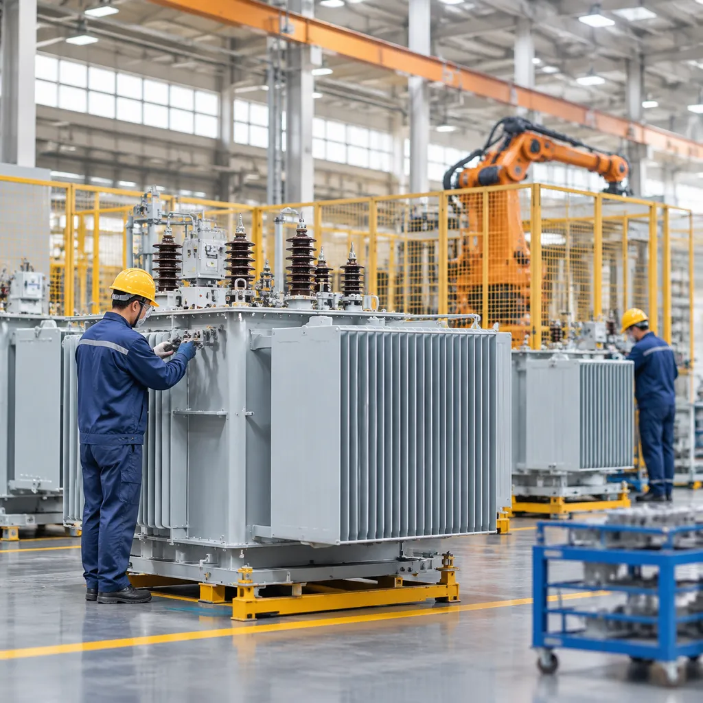
A transformer 2000 kVA unit serves as a critical backbone for commercial power distribution, industrial plants, and utility substations. We build and specify these units to step down medium-voltage distribution feeds into highly stable, utilization-level voltages.
| Parameter | Standard Specification |
|---|---|
| Rated Apparent Power | 2000 kVA |
| Number of Phases | 3-Phase |
| Operating Frequency | 50 Hz / 60 Hz |
| Primary Voltage (HV) | 4.16 kV, 11 kV, 13.8 kV, 22 kV, 33 kV, 34.5 kV |
| Secondary Voltage (LV) | 480Y/277 V, 415Y/240 V, 400Y/230 V, 600Y/347 V |
| Tapping Range | ±2 × 2.5% (Off-Circuit or On-Load Tap Changer) |
| Cooling Method | Dry-Type: AN / AF; Oil-Immersed: ONAN / ONAF |
| Standard Impedance (%Z) | 5.75% to 6.5% (custom available per design) |
Standard Operating Parameters
We design our 2000 kVA units for seamless integration into 3-phase high-voltage and medium-voltage networks.
- Dual Frequency Support: Factory-configured for 50 Hz (IEC systems across Europe, Asia, Africa) or 60 Hz (IEEE/ANSI systems across the Americas).
- Medium Voltage Step Down: Common primary inputs cover 11 kV, 13.8 kV, and 33 kV configurations, stepping down directly to standard low-voltage utilization buses such as 480 V or 415 V.
- Tapping Flexibility: Integrated manual de-energized tap changers allow voltage trimming at ±2 × 2.5% steps to compensate for line-drop variances.
Electrical Load Calculations: Full Load Current (FLC) and Short-Circuit Withstand
Accurately calculating load currents ensures correct switchgear sizing, cable selection, and downstream breaker coordination.
- Full Load Current Formula:
- I = S / (V × √3)
- Where S = 2,000,000 VA, V = Line-to-line secondary voltage.
- Secondary Full Load Current Values:
- At 480 V: FLC = 2,000,000 / (480 × 1.732) = 2,405.7 A
- At 415 V: FLC = 2,000,000 / (415 × 1.732) = 2,782.5 A
- At 400 V: FLC = 2,000,000 / (400 × 1.732) = 2,886.8 A
- Primary Full Load Current (HV side examples):
- At 13.8 kV: FLC = 2,000,000 / (13,800 × 1.732) = 83.7 A
- At 11 kV: FLC = 2,000,000 / (11,000 × 1.732) = 105.0 A
- Short-Circuit Withstand: With a typical 5.75% impedance, prospective symmetrical short-circuit current reaches approximately 17.4 times full load current (over 41.8 kA at 480 V), demanding robust mechanical bracing against electromagnetic forces during fault conditions.
Vector Group & Connection Architecture
The winding connection directly influences neutral grounding, harmonic circulation, and parallel operation:
- Dyn11: Primary Delta, Secondary Star (Wye) with neutral brought out; 30-degree leading phase displacement. This is our default standard for distribution, effectively trapping triplen harmonics (3rd, 9th, 15th) within the primary delta while supplying an unbalanced 4-wire neutral load.
- Dyn1: Similar to Dyn11, but secondary lags primary by 30 degrees; common in legacy networks requiring parallel tie-ins.
- Yyn0: Star-Star with zero phase shift. Suitable when both primary and secondary share a common ground reference, though typically paired with a tertiary delta winding to mitigate harmonic saturation.
Impedance Voltage (%Z) Standards and Fault Mitigation
Impedance dictates system fault levels, voltage regulation, and bus stability:
- Standard Range: Between 5.75% and 6.5% per IEEE C57.12 and IEC 60076 standards.
- Fault Current Limiting: Higher impedance reduces symmetrical short-circuit levels, lowering the interruption duty required for secondary main switchgear.
- Voltage Drop Balancing: Keeping %Z within the 5.75%–6.0% band avoids excessive voltage drop during heavy motor inrush cycles while preserving circuit breaker coordination downstream.
Loss Performance & Efficiency Metrics
Modern 2000 kVA transformers must conform to stringent international efficiency guidelines to minimize lifecycle thermal generation and operating expenses.
- DOE 2016 Standards (10 CFR Part 431): Enforces a minimum efficiency of 99.40% to 99.46% at 50% load for liquid-immersed and medium-voltage dry-type units.
- EU EcoDesign Tier 2 (EN 50588-1): Enforces strict maximum limits on no-load losses (core losses, P0) and load losses (copper losses, Pk), eliminating wasteful core excitation energy.
- IEC 60076-20 Alignment: Provides standard loss classification tiers (e.g., Peak Efficiency Index – PEI), ensuring our assemblies maximize throughput efficiency across variable industrial operating cycles.
Comparative Architecture: Dry-Type vs. Oil-Immersed 2000 kVA Transformers
Choosing between dry-type and liquid-filled architectures for a 2000 kVA rating comes down to fire codes, installation footprint, and ambient operating conditions. Evaluating these structural differences helps identify the right fit for your site. You can also explore our guide on understanding transformers types differences and usage scenarios to see how these designs align with specific operational demands.
Cast Resin Dry-Type Transformers (CRT / VPI)
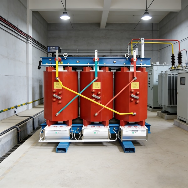
A 2000 kva dry type transformer uses solid dielectric encapsulation instead of liquid cooling, eliminating spill containment structures and reducing fire risk.
- Dielectric Medium: Coils are vacuum-pressure impregnated (VPI) with high-grade polyester varnish or fully encapsulated in cast resin (CRT) under vacuum to eliminate partial discharge.
- Thermal Classes: Built to Class F (155°C) or Class H (180°C) insulation systems with allowable temperature rises of 80°C, 100°C, or 115°C over a 40°C ambient base.
- Fire Safety: Self-extinguishing epoxy resin eliminates the risk of fuel-fed fires, making these units standard for indoor utility vaults, basements, and critical process plants.
Oil-Immersed Distribution Transformers
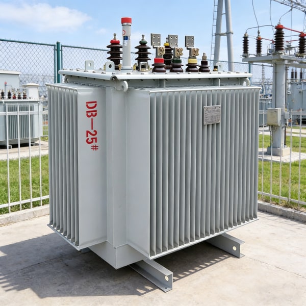
A 2000 kva oil immersed transformer utilizes liquid dielectric insulation to achieve superior heat dissipation and natural protection from moisture, dust, and corrosive industrial atmospheres.
- Dielectric Fluids: Standard refined mineral oil provides economical, high-grade insulation. Natural ester fluids (such as FR3) provide a high fire point (>300°C), offer biodegradable operation, and improve high-temperature loading performance.
- Cooling Classes: Basic units rely on natural convection via an ONAN cooling system (Oil Natural Air Natural). Adding cooling fans (ONAF) provides an immediate 25% to 33% capacity boost for peak demand handling.
Configuration Formats
Mechanical enclosures for 2000 kVA units are engineered to match physical space and switchgear interfaces:
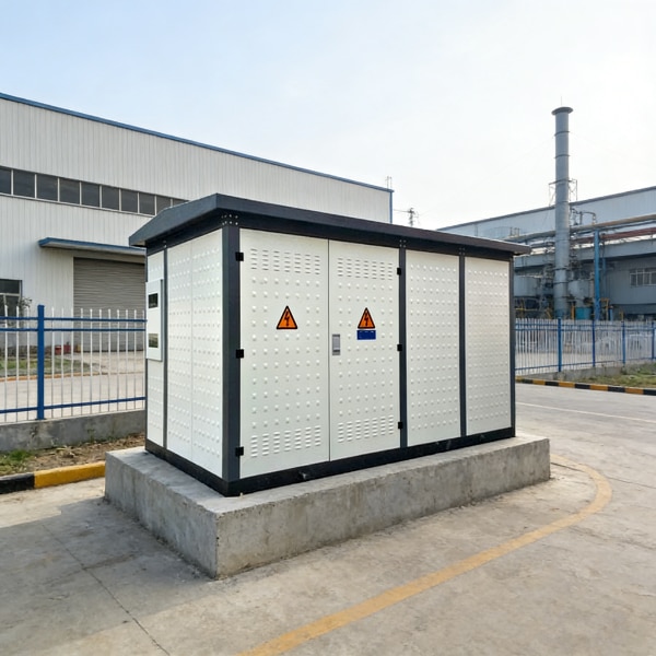
- Pad-Mounted: A tamper-resistant, low-profile pad mounted transformer 2000 kva design featuring compartmentalized high- and low-voltage cable sections, engineered for direct outdoor ground placement.
- Substation Type: Includes side-mounted or top-mounted cable transition boxes and throat connections to couple directly with primary and secondary switchgear line-ups.
- Conservator Tank: Uses an external fluid expansion reservoir fitted with silica gel breathers or internal rubber diaphragms to isolate insulating oil from atmospheric oxygen and moisture.
Direct Comparison Matrix
| Engineering Factor | Cast Resin Dry-Type (2000 kVA) | Oil-Immersed (2000 kVA) |
|---|---|---|
| Dielectric Material | Epoxy cast resin / Nomex varnish | Inhibited mineral oil or synthetic/natural ester fluid |
| Installation Clearances | Minimal; fits within compact electrical vaults | Requires blast walls or dedicated oil containment basins |
| Acoustic Noise Levels | 62 to 66 dB(A) | 58 to 62 dB(A) (naturally quieter core dampening) |
| Environmental Vulnerability | Sensitive to heavy dust, moisture, and chemical vapor | Fully sealed against ambient moisture and corrosive gases |
| Routine Maintenance | Visual inspections, bolt re-torquing, and periodic vacuuming | Dielectric breakdown testing, moisture testing, and DGA fluid sampling |
| Footprint & Total Weight | Taller, wider enclosure profile; ~6,000–7,500 kg | Compact footprint, higher unit weight; ~6,800–8,500 kg |
Core Materials, Construction & Engineering Variations
When specifying a transformer 2000 kVA unit, your material choices dictate physical footprint, longevity, and operational efficiency over decades of continuous load. We tailor these core engineering parameters to align directly with site duty cycles and utility requirements.
Magnetic Core Topology: CRGO Silicon Steel vs. Amorphous Alloy Cores
The magnetic core serves as the backbone of no-load loss reduction. We configure core structures using two primary materials:
- Cold-Rolled Grain-Oriented (CRGO) Silicon Steel: The industrial standard for 2000 kVA builds. High-grade, laser-scribed CRGO laminations cut eddy currents and hysteresis losses while maintaining high mechanical strength under short-circuit stress. They deliver a compact footprint and reliable acoustic performance.
- Amorphous Alloy Cores: Engineered using non-crystalline metallic alloy ribbons. Amorphous metal drops no-load losses by up to 60–70% compared to conventional CRGO. While the core size is physically larger and requires specialized clamping frames to protect against mechanical strain, it is ideal for operations with extended idle periods or light average loading.
Conductor Material Selection: Copper (Cu) vs. Aluminum (Al) Windings
Choosing conductor materials for a transformer 2000 kVA involves evaluating thermal expansion, footprint limitations, and initial capital budget:
- Copper (Cu) Windings: Delivers superior electrical conductivity and mechanical yield strength. Copper coils withstand intense electromechanical forces during grid faults, offer compact overall dimensions, and generate lower load losses under continuous high-amp operation.
- Aluminum (Al) Windings: Provides an economical alternative with excellent heat dissipation. Aluminum requires a larger cross-sectional area to match the current capacity of copper, resulting in a heavier, larger core-and-coil assembly, but it lowers upfront equipment costs without sacrificing standard thermal ratings.
| Parameter | Copper (Cu) Windings | Aluminum (Al) Windings |
|---|---|---|
| Conductivity | Higher (~100% IACS) | Moderate (~61% IACS) |
| Tensile Strength | High (resists short-circuit forces) | Moderate (requires reinforced bracing) |
| Core & Coil Size | Compact footprint | Larger overall physical volume |
| Cost Profile | Higher initial investment | Lower initial purchase cost |
Tap Changer Configurations: Off-Circuit (OCTC) vs. On-Load (OLTC)
Maintaining stable secondary voltage across variable primary distribution networks requires the correct tap-switching configuration:
- Off-Circuit Tap Changer (OCTC): Standard on most 2000 kVA distribution transformers. Allows manual adjustments (typically ±2 × 2.5%) when the transformer is completely de-energized. Best suited for stable primary grids where seasonal shifts dictate infrequent ratio tweaks.
- On-Load Tap Changer (OLTC): Essential for installations facing persistent primary voltage swings or sensitive industrial facilities requiring tight voltage regulation. OLTC systems switch taps dynamically under load via vacuum or resistance-type diverter switches, eliminating operational downtime.
Ingress & Enclosure Engineering: NEMA Ratings and IP Protection Codes
Enclosure design protects the core, coils, and terminal connections against environmental elements, moisture ingress, and accidental contact:
- Indoor Installations (IP20 / NEMA 1): Standard ventilated steel enclosures for indoor substations and electrical rooms, providing baseline protection against accidental contact while maximizing natural air convection.
- Outdoor Installations (IP54 / NEMA 3R): Weatherproof enclosures built with treated steel or aluminum, complete with louvered ventilation, pest screens, and rain hoods.
- Severe Industrial Environments (IP56 / NEMA 4X): Fully sealed or stainless steel construction designed for chemical plants, coastal substations, or dust-heavy industrial settings.
For facilities requiring specific distribution configurations, leveraging proven power transformer solutions from Poland factory ensures heavy-duty enclosures and precision-wound coil architectures that meet exact regional grid compliance standards.
Engineering Sizing, Environmental Derating & Load Management
Deploying a transformer 2000 kva unit requires calculating real operating conditions rather than relying purely on nameplate ratings. Ambient heat, thin air at elevation, and non-linear modern loads will derate a unit quickly if not designed into the core and coil assembly from day one.
Ambient Conditions & Altitude Derating Factors
Standard designs assume operation below 1,000 meters (3,300 feet) and an average ambient temperature of 30°C over 24 hours (40°C peak). When installations exceed these limits, heat dissipation drops significantly due to lower air density.
- Elevation Derating: For every 100 meters above 1,000 meters, cooling efficiency drops. For dry-type units, we derate capacity by roughly 0.5% per 100 meters. For oil units, it is roughly 0.4% per 100 meters, alongside required adjustments for external clearance creepage. Sites operating in demanding high-altitude operations—such as heavy mining environments—frequently rely on specialized engineering seen in our power transformer solutions for Chile mining industry factory supply to counter high-elevation dielectric stress.
- Ambient Temperature Derating: When peak ambient temperatures hit 45°C or 50°C, the allowable winding temperature rise must be lowered accordingly. For every degree Celsius above the 40°C standard maximum, we drop the continuous loading factor by 1.0% to 1.5% to avoid rapid insulation thermal degradation.
| Operating Altitude | Thermal Derating Factor | Dielectric Clearance Adjustment |
|---|---|---|
| Up to 1,000 m (Standard) | 1.00 (100% capacity) | Standard factory clearance |
| 1,500 m | 0.975 (97.5% capacity) | +5% standard clearance |
| 2,000 m | 0.950 (95.0% capacity) | +10% standard clearance |
| 3,000 m | 0.900 (90.0% capacity) | +20% standard clearance |
Harmonic Loading and K-Factor Ratings
Modern facilities run variable frequency drives (VFDs), data racks, and LED banks that generate intense harmonic currents. These non-sinusoidal currents produce eddy-current losses in windings and stray load losses in structural steel, superheating the unit.
- Standard (K-1): Intended strictly for linear loads such as induction motors, resistance heaters, and incandescent lighting.
- K-4 Rating: Designed to handle moderate harmonics up to 50% non-linear loading without exceeding insulation temperature rise limits.
- K-13 Rating: Engineered for 100% non-linear loading typical in industrial process lines, automation plants, and dense motor-drive environments.
- K-20 Rating: Heavy-duty construction utilizing parallel transpositioned conductors, neutral conductors rated at 200% of line current, and electrostatically shielded windings for extreme data center or UPS environments.
Overload Margins and Forced-Air Cooling Upgrades
To manage peak generation cycles or operational expansions without replacing the transformer, cooling stages provide immediate headroom on a baseline 2000 kVA frame.
- Dry-Type Units (AA/FA): Adding automated radial cross-flow cooling fans switches the rating from self-cooled (AA) to forced-air (FA). This introduces a 33% capacity boost, allowing continuous operation at 2666 kVA.
- Oil-Immersed Units (ONAN/ONAF): Upgrading oil-natural cooling with externally mounted multi-bank radiators and thermostatically triggered fans expands heat exchange, pushing the continuous thermal ceiling to 2666 kVA without violating the 65°C average winding rise limits.
- Thermal Relay Triggers: Temperature controllers read winding RTDs directly to engage stage-one fans at preset limits (typically 100°C for dry-type, 85°C for oil), protecting the core from overload aging.
Protection, Instrumentation, and Commissioning for a 2000 kVA Transformer
Operating a 2000 kVA transformer reliably demands a rigorous protection scheme and verified field commissioning. Whether handling heavy industrial loads or grid distribution, integrating the right instrumentation protects core windings from thermal stress and fault transients.
Integrated Monitoring Instrumentation
We equip each transformer 2000 kVA build with dedicated monitoring instrumentation designed to flag anomalies before catastrophic failure occurs:
- Winding & Oil Temperature Indicators (WTI / OTI): Dual-dial gauges track top-oil and hot-spot winding temperatures. Each unit includes independent, microswitch-equipped alarm and trip stages wired to customer terminal blocks.
- Pressure Relief Device (PRD): Mounted on the tank cover with a mechanical pop-up indicator and microswitch contacts, venting rapid internal pressure spikes safely away from personnel.
- Buchholz Relay: Standard on conservator-tank oil units to capture slow gas buildup from insulation breakdown and instantly trip the upstream breaker during sudden oil surges.
- Liquid Level Gauges & Temperature Sensors: Magnetic liquid gauges monitor dielectric fluid margins, while dry-type models utilize multi-channel temperature controllers wired to embedded PT100 RTDs, as found in our SCB18 dry-type transformer builds.
Factory Acceptance Testing (FAT) vs. Site Commissioning
Every 2000 kVA unit must pass stringent verification protocols before leaving the production line and before energization on-site.
- Routine Testing (100% of Units):
- Winding resistance measurement on all tap positions
- Voltage ratio verification and vector group phase-angle checks
- No-load loss and excitation current measurement at rated voltage
- Load loss and percentage impedance (%Z) testing at base rating
- Applied potential and induced overvoltage dielectric testing
- Type & Special Testing (Design Verification): Full lightning impulse tests, sound level surveys, and short-circuit withstand evaluations validate mechanical bracing under bolted-fault conditions.
- Site Commissioning Checklist: Insulation resistance (Megger at 2.5kV/5kV), polarization index (PI), turns ratio testing (TTR), dielectric breakdown voltage (BDV) on fluid samples, and control wire loop checks.
Quality Standards Compliance: IEEE C57.12 & IEC 60076
Our testing workflows align strictly with international engineering codes:
- IEC 60076 Protocols: We verify temperature rise limits, dielectric clearances, and guaranteed loss profiles according to IEC 60076-1 through 60076-5.
- IEEE C57.12 Series: For North American specifications, insulation systems and terminal construction comply with IEEE C57.12.00 general requirements and IEEE C57.12.90 test codes.
Procurement Criteria & Total Owning Cost (TOC) Framework
When procuring a transformer 2000 kva unit, looking only at the initial purchase price guarantees higher lifetime expenditure. Energy losses sustained over a 20-to-30-year operational life routinely exceed the initial capital expense. A rigorous procurement strategy balances upfront capital expenditure (CAPEX) with long-term operational costs (OPEX) via a standardized evaluation formula.
CAPEX vs. OPEX: Applying the TOC Capitalization Formula
We calculate the Total Owning Cost (TOC) using established utility capitalization formulas. This ties no-load losses (core losses) and load losses (winding losses) directly to your local energy tariff and operational profile:
$TOC = Purchase Price + (A × P_0) + (B × P_k)$
- $P_0$: No-load loss in kilowatts (core loss active 24/7, independent of load).
- $P_k$: Load loss in kilowatts at rated current and reference temperature.
- $A$-factor: Present value of each kilowatt of no-load loss over the transformer’s design life (typically \$4,000–\$10,000/kW, depending on energy rates and discount factors).
- $B$-factor: Present value of each kilowatt of load loss, weighted by loading profile and duty cycle (typically \$1,500–\$4,000/kW).
| Evaluation Parameter | Standard Loss Unit | High-Efficiency Optimized Unit |
|---|---|---|
| Initial Purchase Price (CAPEX) | Lower initial outlay | 12% to 25% premium |
| Winding Conductor | Standard aluminum or copper | Optimized high-grade copper |
| Core Material | Conventional CRGO steel | Low-loss laser-treated CRGO / Amorphous |
| 20-Year Operational Losses (OPEX) | Significantly higher | 20% to 35% reduction in wasted energy |
| Net Total Owning Cost (TOC) | Higher lifetime cost | Lowest lifecycle expense |
Evaluating an RFQ through TOC often proves that a unit with higher initial manufacturing costs provides substantial net savings within 3 to 6 years of continuous operation.
Engineering RFQ Checklist: Crucial Parameters
To prevent revisions, design delays, and unexpected field retrofits, provide a precise specification sheet during the initial quoting phase. Following a comprehensive guide to meeting your transformer needs helps streamline these engineering requirements:
- Rated Power & Cooling: 2000 kVA base rating; specify if forced-air cooling stages (e.g., ONAN/ONAF or AN/AF) are required for contingency expansion.
- System Voltages & Taps: Primary voltage (such as 11kV, 13.8kV, or 33kV) and secondary voltage (such as 480V or 415V), along with tapping range (e.g., ± 2 × 2.5%).
- Vector Group & Impedance: Vector group configuration (e.g., Dyn11) and targeted impedance voltage percentage (%Z) to meet downstream switchgear fault ratings.
- Winding Material: Explicit specification for copper (Cu) or aluminum (Al) windings based on weight and thermal conductivity requirements.
- Site Installation Conditions: Ambient temperature extremes, installation altitude if exceeding 1,000 meters (3,300 feet), seismic zones, and indoor vs. outdoor placement.
- Loss Guarantees: Maximum permissible no-load and load loss thresholds to guarantee compliance with regional energy mandates.
Custom Manufacturing & Sourcing Options with JL Transformer
As a dedicated transformer 2000 kva manufacturer, JL Transformer engineers both oil-immersed and cast resin solutions built directly around your operational profile. Rather than pushing off-the-shelf catalog units, we customize magnetic flux densities, core geometry, and tank physical footprints to match existing pad locations or tight indoor electrical rooms.
Working as an established manufacturer of power transformer equipment, our factory-direct engineering enables custom tap changer integration (OCTC or OLTC), specialized harmonic K-factor ratings for non-linear industrial loads, and tailored accessory packages including digital temperature controllers and advanced protection relays. Every unit leaves our facility fully tested to IEC 60076 and IEEE C57 standards, ensuring prompt field installation and long-term operating reliability.
Frequently Asked Questions About 2000 kVA Transformers
What is the full load current of a 2000 kVA transformer at 480V?
For a 3-phase system, the full load current (FLC) on the secondary side is calculated using the standard formula:
- Calculation: 2,000 kVA / (0.480 kV × √3) = 2,406 Amps
- Primary Side Reference (e.g., at 13.8 kV): 2,000 kVA / (13.8 kV × √3) = 83.7 Amps
We recommend sizing main secondary circuit breakers at 3,000 A or using multiple parallel conductor runs per phase to safely accommodate continuous operational capacity, derating factors, and thermal headroom.
Can a 2000 kVA dry-type transformer be installed outdoors?
Yes, but only with a properly engineered weatherproof housing. While oil-immersed designs are inherently suited for direct outdoor exposure, an indoor-rated core will fail rapidly in ambient conditions without physical defense.
- Required Enclosures: Minimum NEMA 3R or IP54-rated metal enclosures with louvered ventilation and anti-condensation space heaters.
- Factory Options: We supply units such as our SCB-13 dry-type transformer built into custom-sealed, weather-hardened enclosures designed for dirty, coastal, or exterior yard deployments.
What is the standard impedance (%Z) for a 2000 kVA unit?
The nominal short-circuit impedance (%Z) for a transformer 2000 kVA typically sits at 5.75% to 6.0% per IEEE C57.12 and IEC 60076 standards.
- 5.75% – 6.0% (Standard): Provides the optimal balance between system voltage regulation and secondary fault current limitation.
- Higher Impedance (7.0% – 8.0%): Available on request when working with low short-circuit withstand thresholds on downstream switchgear.
How much does a 2000 kVA transformer weigh?
Total weight depends on the cooling type (dry vs. oil-filled) and the winding material (copper vs. aluminum):
- 2000 kVA Cast Resin Dry-Type: 5,200 kg to 6,800 kg (11,460 – 15,000 lbs), depending on whether an enclosure is attached.
- 2000 kVA Oil-Immersed / Pad-Mounted: 6,200 kg to 8,500 kg (13,660 – 18,740 lbs), where dielectric fluid accounts for roughly 1,500 kg to 2,200 kg of the total mass. Copper-wound configurations are heavier than aluminum variants due to core and conductor density.
Related Sources
- https://www.cargill.com/bioindustrial/fr3-fluid/specifications
- https://www.ecfr.gov/current/title-10/chapter-II/subchapter-D/part-431/subpart-K
- https://webstore.iec.ch/en/publication/27236
- https://standards.ieee.org/ieee/C57.12.01/7140/
- https://www.siemens-energy.com/global/en/offerings/power-transmission/transformers/distribution-transformers/geafol.html