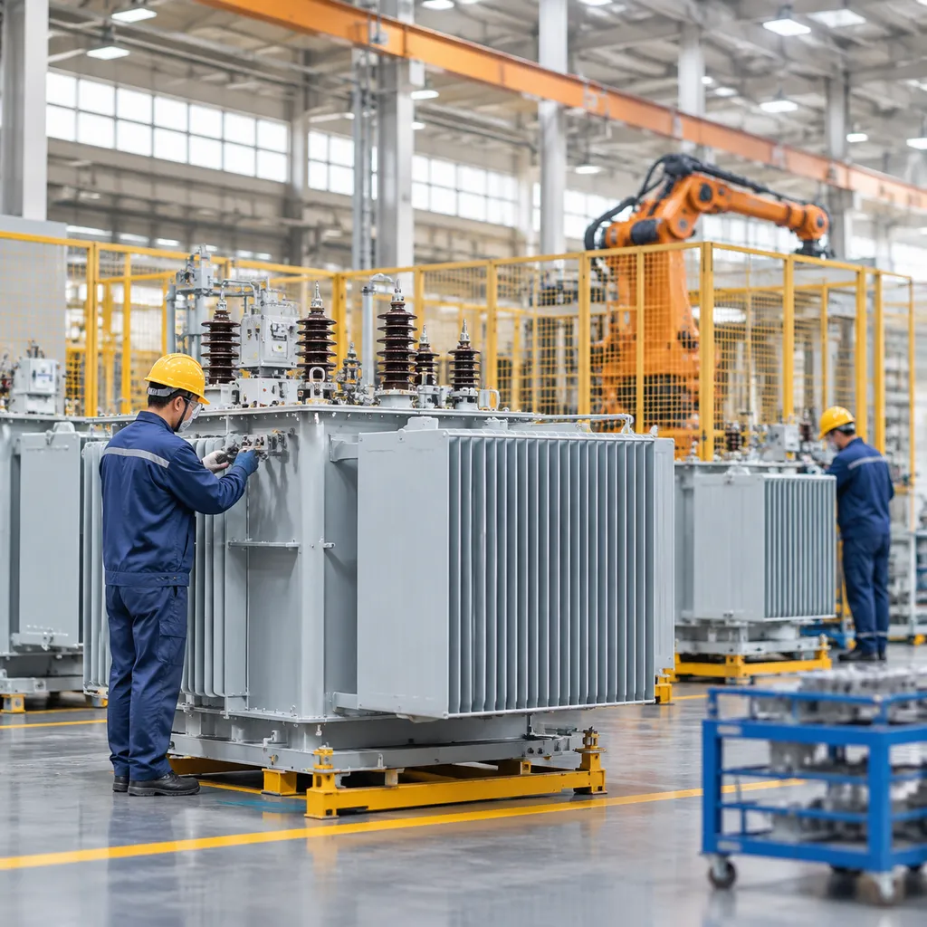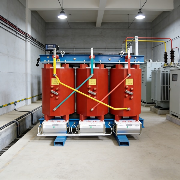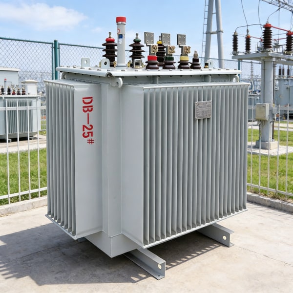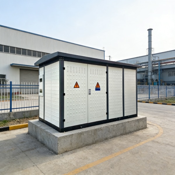

Technical Scenarios Demanding Custom Transformer Engineering
Off-the-shelf magnetic components often fail when modern power conversion projects push beyond standard voltage rails, standard form factors, and typical operating environments. As an experienced custom transformer manufacturer, we engineer application-specific magnetics that eliminate design trade-offs, solve layout bottlenecks, and deliver targeted electromagnetic performance.
Non-Standard Electrical Specifications, High Voltages, and Multi-Winding Taps
Standard catalog components rarely match complex multi-rail power architectures. We develop custom power transformer windings optimized for specific circuit topographies:
– Multiple Output Taps: Dedicated secondary and auxiliary bias windings configured precisely to eliminate secondary DC-DC conversion stages.
– High-Voltage Dielectric Isolation: Specialized insulation barriers engineered to withstand multi-kilovolt sustained potentials and transient surges.
– Parasitic Optimization: Precision interleaving and winding architectures tailored to minimize leakage inductance and inter-winding capacitance for high-frequency switching.
Severe Mechanical Constraints and Low-Profile PCB Footprints
When standard vertical or horizontal bobbin geometries exceed your spatial budget, our team delivers custom-engineered mechanical solutions:
– Ultra-Low-Profile Topologies: Custom planar and low-profile ferrite core assemblies designed for tight enclosure heights under 10 mm.
– Bespoke Bobbins and Headers: In-house tooling for customized pinouts, through-hole (THT) headers, and surface-mount (SMD) footprints.
– Optimized Power Density: Higher copper fill factors and custom core geometries that maximize power density on congested circuit boards.
Harsh Operating Environments: Thermal Cycling and Mechanical Stress
Standard transformers degrade quickly under severe shock, continuous vibration, and thermal extremes. We ruggedize our custom magnetic components through:
– Extended Thermal Operating Ranges: Class F (155°C), Class H (180°C), and Class N (200°C) insulation systems that maintain magnetic properties across -40°C to +150°C ambient sweeps.
– Vibration and Shock Immunity: Structural core bonding, robust potting compounds, and deep vacuum impregnation preventing core cracking and winding displacement.
– Environmental Sealing: Complete encapsulation protecting against humidity, moisture ingress, chemical exposure, and airborne particulates.
Strict Safety, Isolation, and Regulatory Standards
Safety-critical systems demand validated dielectric barriers and fully traceable build processes:
– Medical Regulatory Compliance (IEC 60601-1): 2x MOPP (Means of Patient Protection) and 2x MOOP designs with reinforced insulation, ultra-low leakage currents (<10 µA), and over 8 mm creepage and clearance distances.
– Industrial Safety Standards: Custom builds engineered to meet IEC/UL 62368-1, IEC 61558, and UL 508 requirements.
– Material Traceability: 100% UL-recognized insulation systems (UL 1446) fully compliant with global RoHS and REACH directives.
Standard vs. Custom Engineering Overview
| Parameter | Standard Catalog Transformers | Our Custom Engineered Solutions |
|---|---|---|
| Voltage / Turns Ratio | Fixed standard ratios | Exact arbitrary ratios with optimized multi-tap outputs |
| Form Factor / Footprint | Fixed, generic bobbin outlines | Tailored low-profile heights, custom SMD/THT pinouts |
| Thermal Rating | Typically Class B (130°C) | Class F (155°C), Class H (180°C), or Class N (200°C) |
| Isolation Level | Basic 1.5 kV – 3 kV isolation | Up to 10+ kV reinforced, 2x MOPP/MOOP (IEC 60601-1) |
| Parasitic Control | Variable / non-optimized | Tight tolerance leakage inductance and parasitic capacitance |
Core Topologies and Types in Custom Transformer Manufacturing
As a dedicated custom transformer manufacturer, we build application-specific magnetics configured to resolve thermal, EMI, and power density challenges across modern converter topologies. Selecting the right magnetic geometry is essential; understanding transformer types, differences, and usage scenarios ensures your power stages achieve optimal efficiency and reliability.
Custom High-Frequency and Switch-Mode Power Supply (SMPS) Transformers
We engineer custom high-frequency transformers for switch-mode power topologies operating from 20 kHz to over 1 MHz. Each design focuses on mitigating parasitic losses and managing high-frequency skin and proximity effects.
- Supported Topologies: LLC resonant, Phase-Shifted Full-Bridge (PSFB), Active Clamp Forward, Push-Pull, and discontinuous/continuous Flyback.
- Core Geometries: PQ, ETD, EFD, RM, EP, and planar E-cores utilizing high-permeability, low-loss MnZn and NiZn ferrite core materials.
- Winding Techniques: Multi-strand Litz wire, copper foil windings, and split-bobbin interleaving to drive down leakage inductance and AC resistance ($R_{ac}$).
Custom Toroidal Transformers for Low Magnetic Stray Fields and High Efficiency
Our custom toroidal transformers deliver maximum electrical efficiency within an exceptionally compact footprint. Because the magnetic flux flows uniformly along the continuous grain-oriented silicon steel (CRGO) or nickel-alloy core, these units exhibit virtually zero air gaps.
- Low Radiated EMI: Extremely low stray magnetic field leakage, preventing interference in sensitive analog and audio signal chains.
- High Power-to-Weight Ratio: Up to 50% smaller and lighter than standard laminated transformers with identical power ratings.
- Quiet Operation: Zero mechanical lamination vibration, eliminating audible hum in medical electronics and high-end audio hardware.
Custom Laminated Power and Isolation Transformers (EI, UI, C-Core)
For rugged, low-frequency applications (50 Hz, 60 Hz, and 400 Hz), we manufacture custom laminated power transformers tailored for industrial mains, power distribution, and safe galvanic isolation.
- Core Construction: Precision-stacked, high-grade silicon steel laminations in EI, UI, and C-Core configurations, treated with electrical-grade varnishes.
- Dielectric Isolation: Custom reinforced insulation barriers capable of withstanding dielectric test voltages up to 5 kVAC.
- Mounting Configurations: Chassis mount, PCB through-hole, channel bracket, or DIN-rail integration with customized lead wire terminations.
Planar Magnetics for Ultra-Low Profile and High Power Density Applications
When vertical space is severely constrained, our planar transformer manufacturing process replaces conventional wire-wound bobbins with multilayer printed circuit board (PCB) traces or copper leadframes.
- Ultra-Low Profile: Heights as low as 8 mm to 15 mm, fitting into standard 1U server racks and low-profile DC-DC converters.
- Thermal Dissipation: Direct thermal conduction from flat core plates to external heat sinks and cold plates.
- Consistent Parasitics: Precise copper trace etching guarantees near-zero unit-to-unit variation in leakage inductance and inter-winding capacitance.
Specialty Magnetic Components, Chokes, and Custom Inductors
Beyond core power transformers, our team develops auxiliary custom magnetic components essential for power factor correction, filtering, and circuit protection:
- PFC Boost Inductors: High-saturation Sendust, Kool Mµ, and iron powder toroids engineered for continuous and boundary conduction modes.
- Common Mode Chokes (CMC): High-impedance nanocrystalline and high-permeability ferrite chokes designed to suppress conducted line noise.
- Differential Mode & Output Chokes: Heavy-gauge copper wire and flat helical windings capable of high DC bias currents without saturation.
- Current Sense Transformers: Precision turn-ratio magnetics for closed-loop current feedback and real-time fault detection.
The Custom Transformer Design and Manufacturing Lifecycle
Transforming complex magnetic specifications into reliable hardware requires a structured engineering roadmap. As an experienced custom transformer manufacturer, we take your magnetic requirements from schematic concepts to volume production using a six-stage development workflow.
+———————————————————————————–+
| THE CUSTOM TRANSFORMER MANUFACTURING LIFECYCLE |
+———————————————————————————–+
| [Step 1] Engineering Consultation & Parameter Definition |
| – Voltages, topology, switching frequency, thermal & creepage limits |
| │ |
| ▼ |
| [Step 2] Core Material Selection & Electromagnetic FEA Simulation |
| – Ferrite, amorphous, silicon steel, flux density & core-loss modeling |
| │ |
| ▼ |
| [Step 3] Winding Architecture & Parasitic Leakage Reduction |
| – Interleaving, Litz/foil wire, skin/proximity effect optimization |
| │ |
| ▼ |
| [Step 4] Rapid Prototyping & DFM Review |
| – Functional bench sampling, bobbin fit, DFM clearance validation |
| │ |
| ▼ |
| [Step 5] Vacuum Pressure Impregnation (VPI) & Encapsulation |
| – Void-free varnish penetration, dielectric integrity, thermal fill |
| │ |
| ▼ |
| [Step 6] Scaled Mass Production with Automated Precision Winding |
| – Multi-spindle winding, automated soldering, 100% inline QA testing |
+———————————————————————————–+
Step 1: Engineering Consultation and Parameter Definition
Every project starts with a direct technical assessment between your power engineering team and our magnetics specialists. We define the baseline operating envelope before drafting any physical models:
- Electrical Parameters: Operating topology (Flyback, LLC, Full-Bridge, Push-Pull), nominal and transient input/output voltages, duty cycles, and switching frequencies (20 kHz to >1 MHz).
- Thermal Ceilings: Ambient temperature range (-40 °C to +125 °C), allowable temperature rise ($\Delta T$), and cooling methods (convection, forced air, cold plate).
- Isolation & Regulatory Targets: Creepage and clearance distances, basic or reinforced insulation barriers, and target compliance standards (UL, IEC, CE).
For complex power conversion systems, our early-stage dry-type transformer engineering support helps resolve tight mechanical envelopes and thermal bottlenecks before finalizing the bill of materials.
Step 2: Core Material Selection and Electromagnetic FEA Simulation
Selecting the right core geometry and magnetic compound directly determines efficiency, volume, and total power loss.
| Core Material | Typical Frequency Range | Saturation Flux Density (B_{sat}) | Primary Application Strengths |
|---|---|---|---|
| MnZn Ferrite | 20 kHz – 2 MHz | 0.35 – 0.50 T | Low core loss in high-frequency SMPS, converters |
| Amorphous / Nanocrystalline | 10 kHz – 100 kHz | 1.20 – 1.56 T | High permeability, ultra-compact common mode chokes |
| Silicon Steel (Grain-Oriented) | 50 Hz – 400 Hz | 1.60 – 2.00 T | High power density, mains isolation, line frequency |
| Powdered Iron / Sendust | 10 kHz – 500 kHz | 1.00 – 1.50 T | Distributed air gap, high DC bias, storage chokes |
We utilize 2D and 3D Finite Element Analysis (FEA) simulation software to verify magnetic flux density (B_{max}), assess fringing flux around air gaps, identify localized core hot spots, and verify that the core stays well clear of saturation under peak transient loads.
Step 3: Winding Architecture and Parasitic Leakage Reduction
High-frequency efficiency depends on controlling parasitics. We engineer custom winding patterns to minimize ac copper losses and stray fields:
- Leakage Inductance Reduction: We use primary-secondary sandwich interleaving and split-winding techniques to maximize magnetic coupling.
- Skin and Proximity Effect Control: We integrate multi-strand Litz wire, edge-wound rectangular conductors, or copper foil to maximize effective cross-sectional area at high frequencies.
- Capacitance Management: We balance inter-winding and intra-winding capacitance ($C_p$) to suppress high-frequency ringing and reduce common-mode electromagnetic interference (EMI).
Step 4: Rapid Prototyping and Design for Manufacturability (DFM) Review
Once the simulation converges, we fabricate prototype samples for immediate bench validation. Parallel to sample build, our team performs a rigorous design for manufacturability (DFM) review:
- Validating bobbin pinout mechanical clearances and trace routability on your PCB layout.
- Assessing lead-out wire strain relief and termination integrity.
- Optimizing layer counts and margin tape widths to streamline assembly steps and minimize unit costs in volume production.
Prototype Delivery Checklist:
[✓] Bench validation report (L, Lk, DCR, turns ratio)
[✓] Thermal imaging under rated load
[✓] Hi-pot dielectric baseline log
[✓] Bobbin & pinout dimensional fit verification
Step 5: Vacuum Pressure Impregnation (VPI) and Protective Encapsulation
To protect windings from environmental breakdown and mechanical stress, custom magnetic assemblies undergo advanced insulation processing:
- Vacuum Pressure Impregnation (VPI): We draw deep vacuum to evacuate moisture and air pockets from the winding layers, then inject high-grade dielectric varnish under pressure. This eliminates partial discharge risks, improves thermal dissipation, and stops audible acoustic noise.
- Potting and Encapsulation: For components operating in severe environments (high humidity, conductive dust, high shock/vibration), we use thermally conductive epoxy or silicone encapsulation inside custom-molded shells.
Step 6: Scaled Mass Production with Automated Precision Winding
After final sample sign-off and pilot production approval, we scale the design to automated production lines:
- Multi-Spindle Automated Winders: Programmable tension-controlled winding spindles maintain absolute turns-count precision and consistent layer distribution across every production lot.
- Automated Stripping and Soldering: CNC wire preparation eliminates cold solder joints and insulation pull-back inconsistencies.
- 100% In-Line Parametric Testing: Every manufactured unit passes automated automated test fixtures checking primary/secondary inductance ($L$), leakage inductance ($L_k$), DC resistance (DCR), polarity, and dielectric withstand (Hi-Pot) before packaging.
Quality Assurance, Testing, and Compliance for Custom Magnetics
Every custom magnetic component we produce undergoes rigorous parametric verification and stress qualification before leaving our manufacturing lines. As a dedicated custom transformer manufacturer, our testing regime ensures that every unit matches electrical simulations, operates reliably under harsh loads, and complies fully with international safety mandates.
+———————————————————————————–+
| CUSTOM MAGNETICS TESTING LIFECYCLE |
+————————–+————————–+—————————–+
| 1. PARAMETRIC BENCH | 2. HIGH-VOLTAGE & PD | 3. STRESS & COMPLIANCE |
| • Inductance & Leakage | • Hi-Pot (Up to 5 kVAC) | • Thermal Shock (-40/+155°C)|
| • DCR & Turns Ratio | • Partial Discharge (PD) | • Full-Load Burn-in |
| • Interwinding C | • Insulation Resistance | • UL 1446 / IEC / RoHS |
+————————–+————————–+—————————–+
Parametric Bench Testing
We test 100% of our production runs to eliminate variations in magnetic cores and automated winding tensions. Our core parametric checks include:
- Inductance ($L_m$) and Leakage Inductance ($L_k$): Measured across specified operating frequencies with precision LCR meters to maintain switching balance and suppress parasitic spikes.
- DC Resistance (DCR): Checked across all primary, secondary, and auxiliary windings to ensure minimal $I^2R$ copper loss and correct wire gauge usage.
- Turns Ratio and Polarity: Phase alignment and voltage transformation ratios are validated across multi-tap outputs to prevent incorrect output voltages.
- Interwinding Capacitance ($C_w$): Screened to optimize common-mode noise suppression and electromagnetic compatibility (EMC).
Dielectric Withstand (Hi-Pot) and Partial Discharge Testing
High-voltage safety and dielectric isolation protect both downstream electronic components and field operators:
- Dielectric Withstand (Hi-Pot): We apply high AC/DC test voltages (typically 1.5 kVAC to over 5 kVAC) between primary-to-secondary windings and winding-to-core interfaces to verify the strength of solid insulation, creepage distances, and clearance barriers.
- Partial Discharge (PD) Testing: Crucial for medium- and high-voltage magnetics, PD analysis detects micro-arcs and localized insulation breakdowns within resin voids or tape layers before catastrophic field failure occurs.
- Insulation Resistance (IR): Measured with mega-ohm meters at high DC voltages to confirm complete isolation barrier integrity under dry and humid conditions.
Environmental and Mechanical Stress Qualifications
To guarantee long-term field survivability in demanding industrial, automotive, and renewable setups, our custom magnetic components undergo extreme stress screening:
| Qualification Test | Test Parameters & Standard | Engineering Purpose |
|---|---|---|
| Thermal Shock & Cycling | -40°C to +155°C (100+ cycles) | Validates epoxy encapsulation, bobbin stability, and solder joints |
| Full-Load Burn-In | 100% rated power at elevated ambient ($50°C–85°C$) | Weeds out infant mortality defects and checks thermal rise ($\Delta T$) |
| Mechanical Vibration & Shock | 10 Hz–500 Hz swept sine, 50G mechanical shock | Verifies lead integrity, core retention clips, and header solder durability |
| Humidity & Moisture Resistance | 85°C / 85% RH steady-state exposure | Tests resistance against moisture ingress and surface tracking |
Global Safety Certifications and Material Compliance
We streamline your end-product safety approvals by designing custom magnetics that align directly with worldwide regulatory frameworks:
- UL 1446 Electrical Insulation Systems: Pre-certified Class B (130°C), Class F (155°C), and Class H (180°C) insulation systems that eliminate months of redundant agency testing for your power assemblies.
- IEC & Medical Standards: Strict isolation design conforming to IEC 61558-1/2, IEC 62368-1 for IT/AV equipment, and IEC 60601-1 (2x MOPP/MOOP) for medical electronics.
- Regional Grid & Industrial Directives: Complete documentation and testing matching verified transformer compliance standards for CE-marked and global industrial equipment.
- RoHS and REACH Compliance: Strict bill-of-materials traceability ensures all bobbins, copper wires, magnetic cores, potting resins, and varnishes are 100% compliant with hazardous substance limits.
How to Choose the Right Custom Transformer Manufacturer
Selecting an OEM transformer supplier requires looking beyond catalog specs. When off-the-shelf parts fail to meet non-standard footprints, strict isolation barriers, or thermal limits, you need a true engineering partner rather than a transactional build-to-print shop. We evaluate custom magnetics vendors based on four operational pillars to guarantee long-term field reliability and production scalability.
+————————————+———————————————+
| Evaluation Factor | What to Demand from Your Manufacturer |
+————————————+———————————————+
| Engineering Capability | In-house FEA simulation, DFM, loss modeling |
| Prototyping Turnaround | Functional samples shipped within 1–2 weeks |
| Tooling & Fabrication | In-house CNC/molding for custom bobbins |
| Quality & Traceability | UL 1446 Class B to H, ISO 9001, full Lot ID |
+————————————+———————————————+
Engineering Depth vs. Build-to-Print Vendors
A standard contract manufacturer only builds what is on your print—including latent design flaws, resonance issues, or thermal bottlenecks. An experienced custom transformer manufacturer acts as an extension of your R&D team:
- Design for Manufacturability (DFM): Analyzing winding windows, copper fill factors, and bobbin pinouts to eliminate production bottlenecks early.
- Parasitic Optimization: Adjusting interleaving and split-winding techniques to drastically slash leakage inductance and inter-winding capacitance.
- Thermal Simulation: Running electromagnetic FEA models to predict core/copper hotspots before cutting any tooling.
Prototyping Agility and Production Scaling
Rapid time-to-market demands agile custom transformer prototyping that mirrors final mass-production units:
- Sample Velocity: First-article prototypes delivered within 5 to 10 working days for benchtop validation.
- Seamless Scaling: Direct transition from lab-wound pilot builds to automated multi-spindle winding machines without changing electrical characteristics.
- Mass Consistency: Consistent inductance, turns ratio, and DC resistance across volume runs, verified through automated batch testing.
Material Traceability, Supply Chain Security, and Certifications
A robust supply chain prevents field failures and regulatory delays. When building high-reliability hardware—such as our power transformer solutions for demanding industrial environments—material integrity is paramount:
- Insulation Systems: Pre-approved UL 1446 insulation systems (Class 130°C to 200°C) to eliminate costly, time-consuming safety testing on your end.
- Strict Material Traceability: 100% batch tracking for magnet wire, magnetic cores (ferrite, silicon steel, amorphous), high-dielectric tapes, and potting resins.
- Global Compliance: Full adherence to RoHS, REACH, and relevant IEC/EN safety isolation standards.
In-House Tooling for Custom Bobbins, Headers, and Mounts
Mechanical constraints often break a design when standard bobbins do not fit your enclosure or creepage requirements. We eliminate third-party tooling delays through:
- Custom Bobbin Molding: Fast-turn injection tooling for high-dielectric plastics (PBT, phenolic, LCP).
- Specialized Terminations: Flying leads, custom PCB pins, surface-mount (SMD) pads, or rugged terminal blocks.
- Custom Mechanical Mounting: Precision-stamped clamps, shielding cans, and specialized brackets designed to survive extreme shock and vibration.
Why Partner with JL Transformer for Your Custom Magnetics
As an established custom transformer manufacturer, we eliminate the friction between initial magnetic circuit design and full-scale factory production. We work directly alongside your engineering and procurement teams to deliver high-performance, cost-effective magnetic components tailored to your exact physical and electrical operating boundaries.
Direct Engineering Support to Solve Thermal and Spatial Bottlenecks
Off-the-shelf magnetics force costly design compromises. Our engineering team steps in during your initial design phase to optimize core geometry, thermal dissipation paths, and PCB footprints:
- Spatial Optimization: Custom bobbin creation, low-profile planar layouts, and multi-pin header alignments to fit restricted enclosures.
- Thermal Loss Mitigation: Precision core selection and winding arrangements that eliminate localized hotspots and manage core loss under extreme switching conditions.
- Parasitic Control: Active reduction of leakage inductance and inter-winding capacitance to protect your switching MOSFETs and reduce snubber circuit sizing.
Advanced Manufacturing Facility
Our production lines integrate automation with strict process control to ensure batch-to-batch repeatability for complex magnetic assemblies:
- Automated Multi-Spindle Winding: Precision tension control across multi-filar wire, Litz wire, and copper foil windings for exact turns ratios and uniform DCR.
- Vacuum Pressure Impregnation (VPI): Deep resin penetration to eliminate air voids, damp acoustic hum, boost dielectric breakdown voltage, and protect against humidity.
- In-House Potting and Encapsulation: High thermal conductivity epoxy and silicone fills designed to survive heavy shock, mechanical vibration, and continuous thermal cycling.
Proven Track Record Across Demanding Industries
We engineer custom magnetic solutions across key global sectors that demand zero failure rates:
- Renewable Energy & Solar Inverters: High-efficiency boost and isolation units designed for low daytime losses and extended operational lifespans.
- EV Charging & Automotive: Rugged chokes and transformers built to handle wide input swings and high vibration.
- Industrial Automation: Reliable power transformer industrial solutions engineered for continuous 24/7 factory floor operation.
- Medical Equipment: High-isolation safety transformers complying strictly with low-leakage requirements.
Fast-Turnaround Prototyping with Certified Compliance
We move projects from CAD validation to benchtop prototypes in days, not months. Every build phase is governed by stringent quality frameworks:
- Agile Prototyping: Rapid sample builds supported by 3D-printed bobbin fixtures and dedicated prototype winding cells for fast design verification.
- Certified Insulation Systems: Fully documented materials tracking built around UL 1446 recognized Class B (130°C), Class F (155°C), and Class H (180°C) systems.
- Quality Management: Complete traceability, comprehensive parametric testing, and strict compliance under ISO 9001, RoHS, and REACH standards.
How to Prepare an RFQ for Custom Transformer Manufacturing
When you submit a Request for Quotation (RFQ) to a custom transformer manufacturer, providing clear engineering data right away cuts development time and eliminates redesign loops. Complete specifications allow our engineering team to run accurate electromagnetic simulations, select core geometries, and deliver exact pricing and prototype timelines.
Electrical Operating Parameters and Circuit Topology
We evaluate the full electrical profile to establish winding ratios, core cross-sections, and copper wire gauges. Provide the following core data points:
- Operating Voltages & Currents: Specify minimum, nominal, and maximum input voltages ($V_{in}$), as well as continuous and peak output currents for each secondary winding.
- Power Rating & Switching Frequency: Define the continuous power handling in VA or Watts along with the target switching frequency (e.g., 50/60 Hz for mains power, or 20 kHz to 500 kHz+ for SMPS designs).
- Circuit Topology: Clarify your topology (Flyback, Forward, LLC Resonant, Full-Bridge, Push-Pull, or standard linear step-down/isolation).
- Thermal & Efficiency Targets: Detail your target operating efficiency (e.g., \ge 96%), ambient operating temperature range (-40 °C to +85 °C), and maximum allowed temperature rise ($\Delta T$).
Mechanical Constraints, Mounting, and Safety Compliance
Physical envelopes and regulatory isolation boundaries dictate core configurations, bobbin types, and insulation layers.
- Dimensional Limits: Provide the absolute maximum length, width, and height (L × W × H) bounding box, along with PCB layout constraints and weight limitations.
- Mounting and Terminations: Choose between surface mount (SMD), through-hole (THT) pins, chassis-mount brackets, flying leads, or screw terminal headers.
- Dielectric Isolation & Safety Standards: State mandatory isolation barriers (primary-to-secondary Hi-Pot test voltages, e.g., 3.75 kVAC or 5 kVAC), minimum creepage and clearance distances, and target agency standards such as UL 60950/62368, IEC 60601-1 (medical), or UL 1446 Class F/H insulation systems. For industrial power equipment, reviewing baseline distribution specifications like our SCB-11 dry-type power transformer helps align enclosure ratings and high-voltage dielectric clearances.
Custom Transformer RFQ Specification Checklist
| Specification Category | Key Parameters to Include | Engineering Impact |
|---|---|---|
| Electrical Inputs | $V_{in}$ range, output taps, duty cycle, ripple limits | Determines core volume, flux density ($B_{max}$), and primary/secondary turn ratios |
| Topology & Frequency | Switching frequency, circuit type (LLC, Flyback, Buck) | Dictates core material selection (ferrite grades, powdered iron, amorphous alloys) |
| Thermal & Losses | Max ambient temp ($T_A$), max $\Delta T$, target efficiency | Drives wire selection (Litz vs. solid copper), interleaving, and thermal dissipation paths |
| Mechanical Package | Max L × W × H, pin pitch, terminal styles | Establishes bobbin selection, custom tooling needs, and potting enclosure requirements |
| Safety & Isolation | Hi-Pot dielectric ratings, creepage/clearance, UL/IEC codes | Defines margin tape widths, triple-insulated wire (TIW) usage, and barrier layers |
Frequently Asked Questions About Custom Transformer Manufacturing
What is the typical turnaround time for custom transformer prototypes?
For standard core geometries and in-stock bobbin profiles, our standard turnaround for sample builds is 7 to 10 business days. If your design requires 3D-printed bobbin iterations, custom-machined headers, or specialized planar PCB stackups, prototype sampling typically takes 2 to 3 weeks. We prioritize fast electrical transformer prototyping so your hardware team can validate power stages on the bench without delaying sprint deadlines.
How does a custom transformer minimize EMI and parasitic losses compared to standard catalog parts?
Catalog magnetics force your circuit to accommodate generalized, compromise-heavy winding structures. As a dedicated custom transformer manufacturer, we eliminate those compromises at the physics level:
Interleaved Winding Geometries: Minimizes primary-to-secondary physical distance for aggressive leakage inductance reduction.
Integrated Shielding Layers: Copper foil or drain-wire Faraday shields placed directly between winding layers suppress radiated and conducted common-mode noise.
Optimized Conductor Layout: Utilizing Litz wire, copper foil, or planar traces minimizes high-frequency AC copper losses caused by proximity and skin effects in switch-mode power supply (SMPS) topologies.
Can a custom transformer manufacturer help optimize designs for lower unit production costs?
Yes. Through proactive design for manufacturability (DFM) magnetics reviews, we help engineering teams strip unnecessary cost drivers out of their bills of materials. We optimize wire gauge selections, match standard core windows to eliminate hand-taping steps, and design terminations for automated multi-axis spindle winding. Our engineering processes adhere to global transformer manufacturing excellence standards, driving down unit costs while keeping dielectric margins and thermal performance rock solid.
What minimum order quantities (MOQs) apply when ordering custom magnetic components?
We align our production tiers with your project lifecycle:
Engineering Samples: Small evaluation batches (typically 5 to 10 units) for design verification and initial EMI pre-compliance testing.
Pilot & Pre-Production Runs: Flexible pilot batches (50 to 500 units) to support regulatory certifications (UL, CE, IEC) and field testing.
Scheduled Volume Production: Production runs scaled to your manufacturing forecast, supporting high-volume custom magnetic components with full supply chain traceability and buffer inventory options.