
Core Engineering Capabilities Every Power Transformer Manufacturer Must Have
When utility infrastructure fails, the root cause rarely stems from routine operation—it traces back to design compromises made on the factory floor. As an experienced manufacturer of power transformer units, we know that building grid resilience requires mastering core physical and electromagnetic dynamics long before a unit ever reaches a pad.
A reliable power transformer must survive harsh dynamic fault conditions, severe thermal cycling, and decades of continuous dielectric stress. Achieving this level of reliability demands uncompromising manufacturing standards across three core engineering disciplines.
CRGO Processing and Step-Lap Miter-Cut Stacking
The magnetic core dictates lifetime operational efficiency. To minimize no-load losses and eliminate magnetostriction noise, our core production relies on high-permeability, laser-treated cold-rolled grain-oriented (CRGO) electrical steel.
- Precision CNC Step-Lap Slitting: We cut laminations with automated miter angles, guaranteeing tight tolerances that eliminate air gaps at the joints.
- Multi-Step Lap Stacking: By staggering the core joints across multiple steps, magnetic flux flows smoothly across laminations without saturating joint corners.
- Measurable Results: This precision process slashes core losses by up to 20%, minimizes localized hot spots, and cuts operational acoustic emissions well below standard NEMA and IEEE limits.
Copper Winding Geometries for Short-Circuit Withstand Capability
A power transformer must withstand severe electromagnetic forces during external through-faults. Massive radial burst forces push outward on secondary windings, while intense axial compressive forces can crush end insulation.
To guarantee superior short-circuit withstand capability, we use only premium electrolytic-grade continuous transposed conductors (CTC) and oxygen-free copper:
- Custom Winding Geometries: Depending on voltage class and MVA ratings, we deploy disc, interleaved, or helical winding configurations to optimize surge distribution.
- Radial and Axial Bracing: Windings are pre-shrunk under calibrated axial hydraulic pressure before assembly, ensuring zero mechanical slack during sudden grid faults.
- Uniform Heat Dissipation: Dedicated vertical and radial oil ducts prevent localized thermal degradation of conductor insulation under heavy peak loading.
High-Density Insulation and Dielectric Oil Barrier Systems
A transformer’s operational lifespan matches the lifespan of its solid insulation. Once pressboard degrades from mechanical stress or moisture, dielectric breakdown is inevitable.
Our dielectric barrier systems integrate high-density pre-compressed pressboard, solid molded angle rings, and targeted insulating barriers designed via 3D electrostatic field simulations:
- Automated Constant-Pressure Clamping: Heavy-duty tie plates and spring-loaded clamping structures exert continuous, uniform pressure on core and coil assemblies to prevent mechanical drift over decades of thermal expansion.
- Optimized Creepage Paths: Oil-barrier segmentation eliminates long uninterrupted oil gaps, drastically lowering the risk of partial discharge under extreme transient overvoltages.
- Moisture-Resistant Cellulose: Every insulation component is strictly conditioned to guarantee minimal residual moisture content before tanking.
| Engineering Focus | Technical Execution | Operational Benefit to Asset Owners |
|---|---|---|
| Magnetic Core | Laser-scribed CRGO + Step-lap miter jointing | Dramatically reduced no-load losses and lower operational decibels |
| Windings | CTC copper with pre-compressed sizing | Certified short-circuit durability against severe utility fault currents |
| Insulation Matrix | Pre-compressed pressboard & automated clamping | Zero winding looseness and extended 30+ year dielectric service life |
Power Transformer Portfolio and Application Capabilities
As a dedicated manufacturer of power transformer equipment, we design and build core-form units tailored to real-world grid demands, severe duty cycles, and tight site boundaries. Whether you are stepping up generation capacity or feeding sensitive downstream loads, our engineering covers the full operating spectrum.
High-Voltage Transmission and Generator Step-Up (GSU) Transformers
Our high-voltage power transformers and generator step-up (GSU) units are built to handle continuous thermal stress, frequent system disturbances, and extreme electrical field gradients.
- Voltage ratings: Up to 500 kV class with customized BIL (Basic Impulse Insulation Level) ratings.
- Continuous duty: Built for round-the-clock generation feeds, minimizing thermal hot spots through guided oil flow.
- Grid interconnects: Engineered as robust autotransformers and multi-winding units to bridge transmission systems seamlessly.
Custom Substation Transformers and Compact Urban Footprints
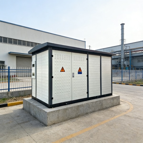
Real estate constraints in urban substations require high power density without sacrificing safety or cooling efficiency. As experienced substation transformer suppliers, we tailor overall tank footprints, bushing placements, and terminal enclosures to fit existing civil pads.
- Noise mitigation: Low-vibration core clamping and sound-dampening enclosures compliant with strict municipal noise codes.
- Flexible arrangements: Top-mounted, side-wall, or throat-connected cable boxes configured to eliminate costly site rework.
- Step-down performance: Reliable performance as industrial step down transformer producers for high-demand municipal and utility distribution points.
Liquid-Immersed Conservator Systems vs. Specialized Dry-Type Units
Choosing between liquid-filled and dry-type units comes down to operating environment, installation codes, and power ratings. Understanding these operational boundaries is essential—our detailed breakdown on understanding power transformers and distribution transformers provides practical insight into how core configurations affect long-term site performance.
| Feature | Oil Immersed Power Transformers | Specialized Dry-Type Units |
|---|---|---|
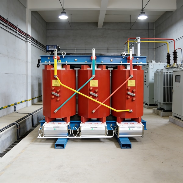
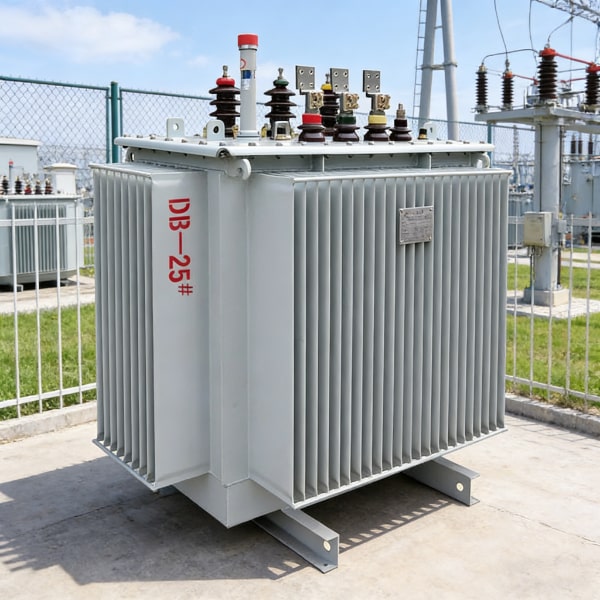
| Cooling Medium | High-grade mineral, synthetic, or natural ester oil | Air-cooled (VPI or cast resin) |
| Primary Placement | Outdoor utility yards and heavy substations | Indoor vaults, basements, and fire-critical zones |
| Overload Capacity | High thermal inertia for handling sustained surges | Moderate; requires forced-air boosting for peaks |
| Maintenance Profile | Periodic oil screening and DGA monitoring | Minimal fluid upkeep; routine cleaning and torque checks |
Engineered for Renewables, Data Centers, and Heavy Industry
Modern loads generate unpredictable operational profiles. We offer custom power transformer fabrication to match these non-linear conditions directly:
- Renewable energy farms: Inverter-duty step-up units built to handle harmonic distortion, high-frequency voltage spikes, and fluctuating solar/wind generation cycles.
- Mission-critical data centers: High-reliability designs with redundant cooling configurations and low impedance tolerances to safeguard uninterrupted computing power.
- Heavy manufacturing & mining: Ruggedized transformers engineered to endure the aggressive load swings of arc furnaces, heavy induction drives, and remote industrial plants.
Factory Acceptance Testing (FAT) and International Standards at Our Plant
As an experienced manufacturer of power transformer units, we know that skipping steps in quality control guarantees premature failures in the field. When you order high-voltage gear, you need verifiable proof that the unit can handle decades of electrical, thermal, and mechanical stress before it ships. That is why our factory floor operates as a fully certified testing facility where every unit undergoes relentless scrutiny.
Mandatory Compliance: IEEE C57 and IEC 60076
We align our manufacturing and validation processes directly with core global benchmarks to ensure seamless grid synchronization anywhere in the world:
- IEEE C57 Series: Tailored for North American utility networks, focusing on short-circuit integrity, dielectric safety clearances, and strict thermal loss calculations.
- IEC 60076 Standards: Applied globally across European, Middle Eastern, and Asian infrastructures for both core loss limits and mechanical sound level compliance.
Every unit built under our power transformer solutions from Poland factory operations comes with complete, traceable documentation proving standard-by-standard compliance.
Routine and Type Testing Protocols
We leave nothing to guesswork. Before crating and freight prep, our test bay subjects every power transformer to intense routine and type evaluations:
- Winding Resistance & Ratio Verification: Verifying phase balance, turns ratios, and tap changer step consistency across all switch positions.
- Lightning Impulse Testing: Simulating severe transient surges and lightning strikes at full BIL (Basic Impulse Insulation Level) ratings to ensure solid surge protection.
- Temperature Rise Runs: Operating windings and oil at continuous rated capacity to verify cooling fin and radiator thermal rejection performance.
| Test Parameter | Standard Target | Verification Focus |
|---|---|---|
| Turns Ratio & Vector Group | Within ±0.5% tolerance | Core winding balance across taps |
| Full-Wave Lightning Impulse | Specified BIL rating | Surge withstand without flashover |
| Applied & Induced Overvoltage | Up to 2x rated operating voltage | Inter-turn and ground insulation integrity |
| Partial Discharge (PD) | < 10 to 50 pC at 1.5 Um / √3 | Void-free insulation barrier screening |
Advanced Partial Discharge and Induced Overvoltage Screening
Internal insulation breakdown is the leading cause of sudden substation fires. We run sensitive partial discharge (PD) testing in shielded test rooms to catch microscopic voids, surface discharges, or trapped gas pockets within the dielectric matrix. Paired with high-frequency induced overvoltage screening, we stress the inter-turn and inter-winding insulation well beyond daily operating voltages. If a core-and-coil assembly displays even trace levels of PD exceeding international limits, it never leaves our shop floor.
Vapor-Phase Drying (VPD) and Automated Vacuum Oil Filling
Water is the enemy of transformer insulation. To ensure decades of trouble-free operation, we use industrial-grade vapor-phase drying (VPD) technology:
- Hydrocarbon Vapor Heating: Kerosene vapor circulates through the vacuum autoclave, condensing evenly across dense cellulose pressboard and copper assemblies to heat them uniformly without thermal shock.
- Deep Vacuum Moisture Extraction: Rapid vacuum cycles draw off deep-seated moisture, bringing insulation water content down below 0.5% by weight.
- Automated Vacuum Oil Filling: We degas, de-moisturize, and inject inhibited mineral or ester oil straight into the sealed tank under continuous deep vacuum. This eliminates trapped air bubbles and stabilizes the dielectric barrier from day one.
Evaluating Total Cost of Ownership Over Factory Nameplate Pricing
When sourcing high-voltage equipment, looking only at the initial purchase quote is a trap. The purchase price makes up barely 15% to 20% of an electrical asset’s true lifecycle expense. As a seasoned manufacturer of power transformer units, we build our hardware to optimize operational expenses over decades of continuous load, rather than simply trimming upfront manufacturing costs.
Calculating Core and Load Losses Across 30-Year Cycles
Every megawatt lost to heat comes out of your bottom line. We evaluate overall expenditure using capitalized loss formulas tailored to your local utility rates:
- No-Load Core Losses (Iron Losses): Occur 24/7/365 regardless of grid demand. We cut these through precision-stacked, high-permeability CRGO steel cores.
- Load Losses (Copper Losses): Scale with the square of the operational current ($I^2R$). We minimize these via optimized cross-section copper conductors and transposition winding techniques.
- Total Ownership Formula: We help operators run life-cycle evaluations using the capitalized cost formula:
$TCO = Initial Cost + (A × No-Load Loss) + (B × Load Loss)$
Where $A$ and $B$ represent the capitalized cost per kilowatt over a standard 30-to-40-year life expectancy.
Thermal Dissipation Engineering and Cooling Configurations
Operating temperature dictates insulation degradation rates. For every 6°C to 8°C rise above thermal limits, the lifespan of insulation paper drops by half. We engineer our oil immersed power transformers with custom-fit cooling regimes to keep hot-spot temperatures well within safe limits:
- ONAN (Oil Natural, Air Natural): Passive radiator cooling ideal for baseload industrial operations and low-maintenance remote substations.
- ONAF (Oil Natural, Air Forced): Automated cooling fans kick on during peak demand, expanding output capacity without adding core bulk.
- OFAF (Oil Forced, Air Forced): Pumped oil circulation and forced air for heavy-duty generator step-up (GSU) and high-load transmission platforms.
| Cooling Mode | Pumping Mechanism | Air Flow | Typical Operating Scenario |
|---|---|---|---|
| ONAN | Natural convection | Natural draft | Base load, rural substations |
| ONAF | Natural convection | High-efficiency fans | Peak grid loads, urban substations |
| OFAF | Submerged centrifugal pumps | Multi-bank fan arrays | Heavy industry, high-load transmission |
Smart Asset Protection: Online DGA and Optical Sensors
Unplanned substation outages run up catastrophic costs. We equip our builds with intelligent condition-monitoring hardware right from the factory floor:
- Online Dissolved Gas Analysis (DGA): Continuous multi-gas monitoring (detecting Hydrogen, Acetylene, Ethylene, and Methane) flags early insulation breakdown, arcing, and thermal hot spots before catastrophic failure occurs.
- Fiber-Optic Temperature Probes: Embedded directly within winding hot spots to give you real-time thermal data under variable renewable loads.
- Digital Bushing & Moisture Monitoring: Tracks dielectric dissipation factor (tan delta) and oil moisture content continuously to automate predictive maintenance schedules.
Supply Chain Resilience and Custom Engineering Agility
Unplanned outages and delayed deliveries cost utilities and industrial operators millions. As an experienced manufacturer of power transformer solutions, we build our entire production workflow around engineering agility and supply chain security. When you need to replace an aging unit or expand capacity within an operational substation, standard catalog equipment rarely fits the bill.
Retrofit Engineering for Legacy Footprints
Replacing a legacy unit often means dealing with severe boundary constraints, odd terminal heights, and non-standard impedance requirements. Rather than forcing you into civil works overhauls, our custom power transformer fabrication adapts the physical and electrical design directly to your pad:
- Customized Impedance Matching: We tune copper winding profiles to align precisely with parallel-running units, preventing unbalance and circulating currents.
- Dimensional Adjustments: High-density insulation layouts let us compress overall tank dimensions to respect tight phase-to-phase and phase-to-ground clearances.
- Bushing Reorientation: Terminations, cable boxes, and conservator plumbing match your existing bus duct configurations down to the millimeter.
- Loss Optimization: For sites targeting aggressive operational savings, our S20 oil immersed power transformer design packages top-tier efficiency into compact structural layouts.
Raw Material Procurement Controls
A transformer is only as reliable as the base materials inside the tank. Material shortages or volatile commodity markets cannot become an excuse for delayed energization. We control quality and schedule via direct mill partnerships:
| Raw Material | Grade Standard | Incoming Quality Gate |
|---|---|---|
| Electrical Steel | High-grade CRGO (Laser-treated) | Epstein frame core loss testing per batch |
| Electrolytic Copper | Oxygen-Free High-Conductivity (OFHC) | Resistance verification and elongation tolerance checks |
| Transformer Oil | Uninhibited/inhibited mineral oil (IEC 60296) | Breakdown voltage (BDV), moisture, and interfacial tension screening |
| Solid Insulation | High-density cellulose pressboard | Tensile strength and dielectric purity testing |
Heavy-Haul Transport and Impact Monitoring
Shipping a 50-to-200-ton core-and-coil assembly demands extreme transit care. Mechanical shock during rail, sea, or road transport can shift core laminations or rupture winding clamps before the asset ever sees voltage.
- Nitrogen-Purged Shipping: We drain the main tank oil for transit, sealing it under positive dry-nitrogen pressure (0.15 to 0.3 bar) with automated pressure gauges to keep moisture from reaching the cellulose insulation.
- Tri-Axial Impact Recorders: Every heavy-haul shipment carries redundant 3D shock recorders tracking longitudinal, lateral, and vertical G-forces across the journey.
- Turnkey Site Logistics: We work directly with specialized heavy rigging crews, validating delivery routes, bridge capacities, and crane placements well before the unit leaves our factory floor.
OEM and Custom Manufacturing Solutions at JL Transformer
Standard catalog units rarely solve the physical footprint constraints, impedance targets, or extreme duty cycles our clients face. As a dedicated manufacturer of power transformer equipment, we build custom solutions from the ground up to match precise utility and industrial specifications. We operate as an end-to-end partner, offering complete OEM and ODM fabrication tailored to client nameplates, regional grid codes, and rugged field conditions.
Full-Scale Automated Winding and Modern Core Stacking
We invest heavily in shop-floor automation to eliminate human variance and maintain structural repeatability across production runs:
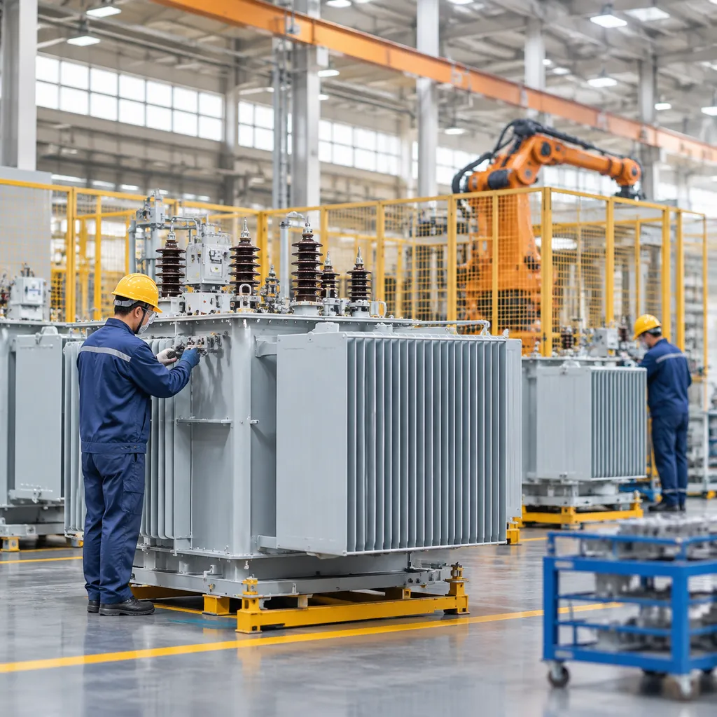
- Automated Vertical and Horizontal Winding: High-precision tension control systems ensure uniform radial stiffness and zero insulation scuffing on both high-voltage disk and low-voltage helical coils.
- Modern Step-Lap Stacking Lines: Automated slitting and robotic step-lap core assembly minimize air gaps, dramatically lowering excitation losses and operational noise levels.
- Integrated Tank Fabrication: Submerged arc welding and multi-stage pressure testing prevent oil leakages under thermal expansion cycles.
Partnering with an experienced custom transformer manufacturer for reliable power solutions gives project developers the flexibility to match exact loss evaluation formulas without paying for oversized, off-the-shelf catalog frames.
Custom High-Voltage Solutions Built to Utility Specifications
We engineer each high-voltage unit to integrate smoothly with existing substation structures and protection schemes.
- Exact Impedance Matching: Seamlessly parallel new installations with existing transformer banks without balance issues.
- Flexible Bushing & Termination Geometry: Custom cable boxes, throat connections, and top-cover high-voltage bushings designed to fit restricted substation perimeters.
- Specialized Duty Ratings: Configurations engineered for high harmonic loads, cyclic industrial overloads, inverter duty, and severe ambient conditions down to -40°C.
Routine Testing, Full Traceability, and Field Support
Every unit rolling out of our manufacturing bays is backed by documented verification and lifetime technical support:
| Quality Assurance Phase | Operational Focus | Engineering Benefit |
|---|---|---|
| Component Traceability | Raw materials tracked by heat and batch numbers (copper, CRGO, oil). | Complete documentation of all metallurgical and dielectric properties. |
| Factory Routine Testing | Ratio, polarity, winding resistance, and dielectric insulation screening. | Guaranteed compliance with IEC and IEEE limits prior to transport. |
| Field Engineering | On-site installation oversight, vacuum oil filling, and commissioning. | Reliable energization with verified baseline field values. |
Our direct engineering engagement ensures your design parameters translate cleanly from the drafting table to full power energization.
Frequently Asked Questions About Choosing a Manufacturer of Power Transformer
What core certifications should you verify before vetting an industrial transformer plant?
Before approving any electrical power transformer factory, we recommend verifying both management standards and type-test certifications:
- Quality & Management Standards: ISO 9001 (Quality), ISO 14001 (Environmental), and ISO 45001 (Health & Safety).
- Technical Compliance: Mandatory alignment with IEEE C57 series or IEC 60076 standards, depending on regional grid requirements.
- Third-Party Test Reports: Validated short-circuit, temperature rise, and lightning impulse test records from recognized independent labs like KEMA, CESI, or equivalent accredited bodies.
Partnering with an experienced manufacturer of power transformer ensures your units arrive fully compliant with utility interconnect mandates.
How do manufacturers guarantee short-circuit withstand capability during sudden grid faults?
We tackle short-circuit withstand capability through a mix of mechanical engineering and strict electromagnetic balance:
- FEA Simulation: 3D Finite Element Analysis models electromagnetic forces during fault conditions to reinforce potential stress points.
- Radial and Axial Bracing: Winding assemblies are built with high-density pressboard spacers and locked into place using heavy-duty steel clamping rings.
- Pre-Shrinking Practices: Windings undergo controlled hydraulic pre-compression to prevent structural shifting under fault-induced mechanical shock.
Understanding these structural protections helps project teams when choosing the right transformer types for severe fault environments.
What is the typical manufacturing lead time for custom high-voltage substation transformers?
Production timelines for custom high-voltage units typically range between 10 to 16 months, depending on base rating and design complexity:
- Engineering & Design Approvals: 4 to 8 weeks for detailed electrical calculations and client layout reviews.
- Material Procurement: 12 to 16 weeks for long-lead materials such as high-grade CRGO electrical steel, specialized copper conductors, and on-load tap changers (OLTC).
- Fabrication & Assembly: 8 to 12 weeks for winding, core stacking, vapor-phase drying, and tanking.
- Factory Acceptance Testing (FAT) & Shipping: 3 to 6 weeks for routine electrical screening and specialized heavy-haul logistics.
How does vapor-phase drying impact the overall operating life of power transformers?
Moisture is the primary enemy of solid paper insulation. The vapor-phase drying (VPD) process extracts moisture far more effectively than traditional hot-air circulation:
- Deep Moisture Extraction: VPD drives residual water content in solid cellulose insulation down below 0.5% by weight.
- Uniform Heating: Hydrocarbon solvent vapor condenses evenly across complex winding geometries, eliminating local hot spots that cause thermal aging.
- Extended Service Life: By preserving paper tensile strength from day one, VPD-treated units easily achieve 35 to 40+ years of operational asset life under rated loads.
Related Sources
- https://e-cigre.org/publication/833-guide-for-transformer-short-circuit-withstand-verification
- https://webstore.iec.ch/en/publication/60076-1
- https://e-cigre.org/publication/796-moisture-measurement-and-assessment-in-transformer-insulation-evaluation-of-chemical-methods-and-moisture-capacitive-sensors
- https://www.hitachienergy.com/products-and-solutions/transformers/power-transformers
- https://www.sciencedirect.com/science/article/pii/S0378779621005234