The Critical Role of Direct-to-Factory Power Transformer Sourcing
Procuring grid-scale electrical equipment demands strict quality control, transparent engineering workflows, and direct accountability. Sourcing directly from an established manufacturer of power transformer equipment eliminates the friction, costs, and risks associated with multi-tiered supply chains.
Intermediary Risks vs. Direct Manufacturer Partnerships
Working through third-party agents often creates communication bottlenecks and inflated project costs. Partnering directly with our production facility ensures technical precision and cost transparency from design to dispatch.
| Sourcing Dimension | Third-Party Intermediaries / Traders | Direct Manufacturer Partnership |
|---|---|---|
| Cost Structure | 15%–30% distributor markups and hidden agent fees | Transparent factory-direct unit pricing |
| Engineering Directness | Delayed communication through non-technical middlemen | Direct consultation with lead electromagnetic design engineers |
| Design Customization | Restricted to off-the-shelf standard catalogs | Full custom power transformer fabrication for unique substation footprints |
| Lead Times & Visibility | Indirect production status tracking | Real-time scheduling oversight and direct factory inspection access |
Key operational advantages of our direct partnership model include:
-
- Direct Design Alignment: Review core and winding layouts directly with our design engineering team to prevent costly specification mismatches.
- Streamlined Change Orders: Expedite revisions to tap changer configurations, bushing orientations, or enclosure dimensions without third-party friction.
- Dedicated Quality Traceability: Access authenticated mill certificates and factory testing data directly from the source.
Balancing Upfront CAPEX with Total Cost of Ownership (TCO)
Procurement decisions based solely on the lowest initial purchase price (CAPEX) frequently result in severe operational expenses (OPEX). A transformer’s lifetime energy losses can exceed its initial purchase price multiple times over its service life.
Total Cost of Ownership (TCO) = Initial Purchase Price (CAPEX) + Capitalized No-Load Losses + Capitalized Load Losses – Decommissioning Asset Value
To maintain an optimized lifecycle balance, we focus on aggressive load and no-load loss optimization:
-
- No-Load Losses (Core Losses / Iron Losses):
- Continuous energy dissipation occurring whenever the unit is energized, regardless of electrical demand.
- We minimize these constant losses using high-grade, laser-scribed, cold-rolled grain-oriented (CRGO) magnetic steel with step-lap mitered core stacking.
- Load Losses (Winding Losses / Copper Losses):
- I²R dissipation generated by current flowing through the transformer windings, varying with the operating load profile.
- We control these operational losses using high-conductivity, oxygen-free electrolytic copper conductors and optimized strand transposed designs.
Optimizing these electromagnetic parameters ensures significant energy savings, lower operating temperatures, and extended insulation life across decades of utility and industrial service.
Core Manufacturing Capabilities in a Power Transformer Factory
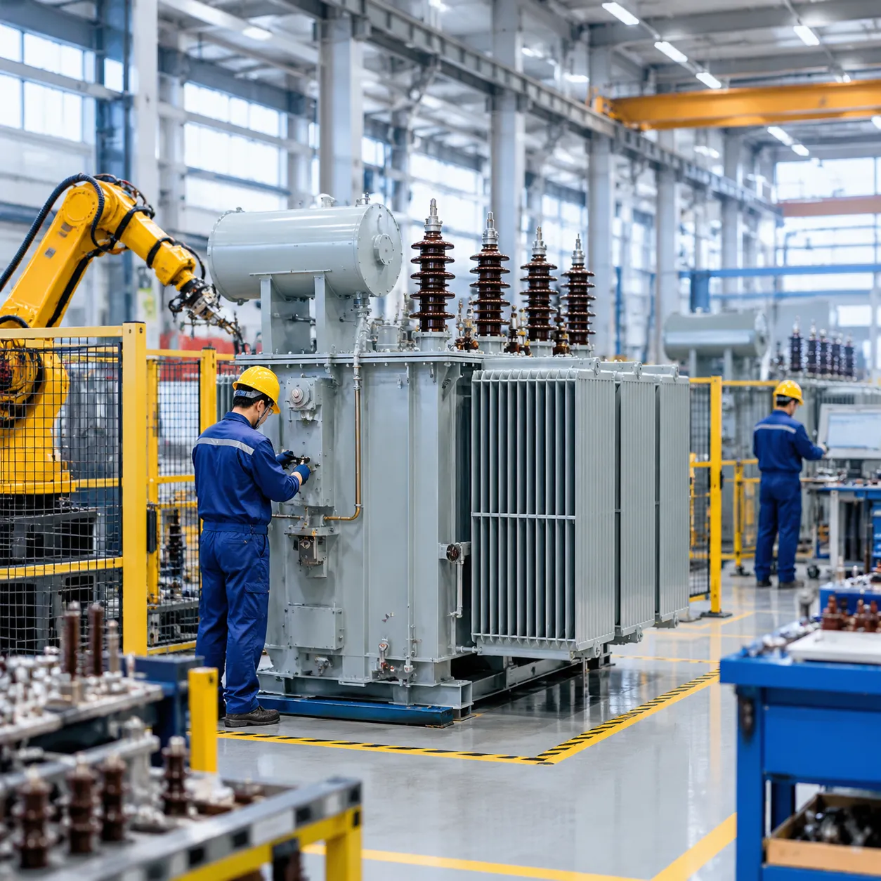
Evaluating a manufacturer of power transformer equipment requires looking directly at factory-floor engineering, material processing, and quality control systems. As an integrated electrical manufacturer, we maintain strict oversight across every stage of fabrication to ensure high efficiency, low losses, and extended operational lifecycles for both industrial networks and transmission grids.
Voltage Classes and Capacity Spectrum
A competent transformer factory must handle diverse voltage ratings and megavolt-ampere (MVA) capacities without compromising dimensional tolerances or dielectric integrity:
-
- Medium Voltage Power Distribution: Ranging from 11kV up to 33kV/35kV, engineered for primary industrial plants, commercial infrastructure, and feeder substations.
- High Voltage Power Transformers: Supporting high-capacity step-up and step-down substation applications from 66kV and 110kV up to 220kV+ transmission grids.
- Turnkey Grid Integration: Delivering specialized power transformer solutions designed for seamless synchronization with regional utility networks and harsh operating environments.
| Parameter | Medium Voltage Distribution | High Voltage Transmission |
|---|---|---|
| Primary Voltage Range | 10 kV – 35 kV | 66 kV – 220 kV+ |
| Typical Capacity | 500 kVA – 20 MVA | 25 MVA – 250+ MVA |
| Primary Duty | Plant distribution, step-down substations | Grid transmission, power plant step-up |
Core Construction & Electromagnetic Design
The magnetic core serves as the foundation for transformer efficiency and excitation loss reduction. We focus on advanced mechanical cutting and stacking methods:
-
- High-Grade CRGO Silicon Steel: We utilize cold-rolled grain-oriented (CRGO) magnetic steel sheets with low specific iron loss and high magnetic permeability.
- Precision Step-Lap Stacking: Automated slitting and step-lap mitred core stacking minimize air gaps, suppress core noise, and sharply reduce no-load excitation currents.
- Rigid Clamping Structures: Heavy-duty steel clamping frames and non-magnetic banding prevent core lamination vibration, maintaining mechanical stability during transport and transient grid faults.
Winding Materials and Insulation Systems
The electromagnetic windings and dielectric barrier define short-circuit withstand capability and thermal longevity:
-
- Oxygen-Free Electrolytic Copper Conductors: We utilize high-conductivity, oxygen-free copper conductors with rounded edges to eliminate local electrical field stress and resist mechanical distortion during external short circuits.
- High-Dielectric Insulation Frameworks: Custom coil assemblies utilize thermally upgraded Kraft paper, high-density pressboard spacers, and Class A or Class F insulation barriers depending on whether the unit uses liquid-immersed or dry-type topologies.
- Automated Tension Coiling: Continuous-disc and helical winding techniques ensure uniform axial pressure distribution and optimal oil flow channels for thermal dissipation.
Transformer Types & Application-Specific Engineering
As an experienced manufacturer of power transformer equipment, we engineer core architectures tailored to exact site constraints, load dynamics, and environmental conditions. Choosing the right design guarantees operational safety, thermal efficiency, and long-term grid reliability across diverse operating environments. For a detailed breakdown of grid installations, review our guide on understanding transformers types differences and usage scenarios.
Oil-Immersed Power Transformers
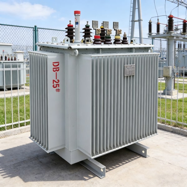
Our liquid-filled units handle high-capacity utility transmission and major industrial distribution networks. We customize the dielectric fluid and cooling system based on your operating ambient profile and load requirements:
- Dielectric Fluids: Standard high-grade inhibited mineral oil for maximum heat dissipation, or synthetic/natural ester fluids offering high flash points for fire-sensitive environments and enhanced biodegradability.
- Dynamic Cooling Configurations:
- ONAN (Oil Natural Air Natural): Passive, low-maintenance convection cooling for baseline continuous loads.
- ONAF (Oil Natural Air Forced): Auxiliary fans automatically engage to handle peak operational surges.
- OFAF / ODAF (Forced Circulation): Pumped oil and directed flow systems for ultra-high-capacity substation transformers demanding rapid heat extraction under continuous heavy loads.
Cast Resin & VPI Dry-Type Transformers
For enclosed facilities where fluid leaks or fire hazards pose severe risks, our dry-type units deliver maximum safety without compromising power delivery:
-
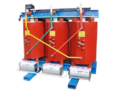
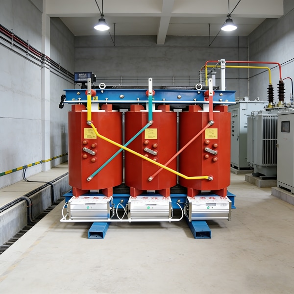
- Cast Resin (CRT): Windings completely encapsulated in epoxy resin under vacuum. Resistant to moisture, heavy dust, and chemical contaminants, making them ideal for underground substations, commercial high-rises, and marine environments.
- Vacuum Pressure Impregnated (VPI): High-temperature insulation treated with specialized polyester resin for superior mechanical strength, quiet operation, and optimal thermal performance in indoor industrial plants.
Specialized Renewable & Heavy Industrial Units
Modern grid integration requires robust protection against erratic power flows and non-linear loads. We build specialized transformers designed for extreme operational cycles:
-
- Solar PV Inverter Step-Up Transformers: Multi-winding configurations (dual or split low-voltage inputs) engineered to interface directly with utility-scale central inverters while mitigating DC bias.
- Wind Farm Step-Up Units: Compact, vibration-resistant designs engineered to fit turbine nacelles or tower bases, built to handle fluctuating wind-generation profiles.
- Harmonic-Resistant Industrial Transformers: Reinforced electro-magnetic shielding and oversized neutral conductors designed to withstand the thermal stress caused by VFDs, arc furnaces, and heavy rectifiers.
International Standards and Quality Assurance Testing Protocols
As a dedicated manufacturer of power transformer systems, we enforce rigorous quality management and factory testing protocols at every stage of production. Every unit is engineered and verified to meet strict utility specifications, ensuring stable operation under extreme electrical and thermal stress.
Global Regulatory Compliance
We align our electromagnetic designs, insulation profiles, and structural builds with major international governing standards:
-
- IEC 60076 Series: Full compliance for international grid networks, substations, and industrial power plants.
- IEEE C57 / ANSI Standards: Exacting design standards for North American utilities and commercial developments.
- ISO Integrated Management: Certified ISO 9001, ISO 14001, and ISO 45001 systems guiding all factory fabrication workflows.
Essential In-Factory Testing Framework
Before leaving our test bay, every unit passes through a multi-tier testing procedure to verify efficiency, dielectric strength, and mechanical stability:
| Test Category | Key Test Procedures | Verification Purpose |
|---|---|---|
| Routine Tests | Winding resistance, voltage ratio, vector group check, insulation resistance, no-load loss, and load loss measurement | Confirms foundational electrical performance and manufacturing accuracy. |
| Type Tests | Full lightning impulse withstand test (BIL) and continuous temperature-rise testing | Validates thermal dissipation and dielectric safety limits under rated operation. |
| Special Tests | Short-circuit dynamic withstand verification, partial discharge (PD) analysis, and sound level checks | Proves structural resilience and low acoustic impact for sensitive grid placements. |
Factory Acceptance Testing (FAT) & Quality Traceability
We provide full transparency during the Factory Acceptance Testing (FAT) phase. Clients can witness testing on-site or through remote high-definition streaming, or delegate verification to recognized third-party inspection bodies such as SGS, TÜV, or Bureau Veritas.
Every completed transformer ships with an exhaustive documentation dossier, including certified Material Test Reports (MTR) for core silicon steel and copper conductors, type-test certificates, and calibrated loss reports. This structured verification process supports our specialized regional deliveries, including our factory-direct wholesale supply programs, ensuring turnkey readiness upon arrival at your substation site.
Vetting Checklist: Key Questions Before Finalizing Your Order
Selecting the right manufacturer of power transformer units requires looking beyond the initial commercial proposal. Before issuing a purchase order, we advise utility planners and EPC engineers to audit factory operations with these critical technical questions:
1. Supply Chain Stability and Material Traceability
-
- Where are the core steel and windings sourced? Ensure the factory maintains verified supply channels for high-permeability CRGO silicon steel and oxygen-free copper. Unchecked material substitution directly degrades no-load and load loss performance.
- Are primary components standardized? Ask for the approved vendor list (AVL) regarding high-voltage bushings, de-energized/on-load tap changers (DETC/OLTC), and Buchholz relays.
2. Custom Engineering Agility and Physical Constraints
-
- Can the design accommodate strict footprint limits? Substation retrofits frequently require dropping a new unit onto an existing foundation pad without relocating busbars, trenching, or radiator banks.
- How are lead times protected against design revisions? Verify that the engineering team conducts early 3D CAD modeling and finite element method (FEM) analysis to finalize mechanical layouts before production starts on units like our S20 oil-immersed power transformer.
3. Post-Commissioning Support and Asset Reliability
-
- What is the on-site engineering scope? Clarify whether the factory provides field supervision during assembly, oil filling under vacuum, and pre-commissioning testing.
- How is long-term maintenance backed? Ensure complete documentation for routine maintenance, dissolved gas analysis (DGA) baselines, and fast-track spare parts availability for high-wear components like gaskets and temperature controllers.
Why Global Projects Partner with JL Transformer
As a dedicated manufacturer of power transformer equipment, we engineer and build heavy-duty electrical assets designed to perform under demanding operational profiles. Global utilities, EPC contractors, and industrial operators work directly with our engineering team to secure high-performance transformer assets built to exact specifications.
Advanced Precision Fabrication
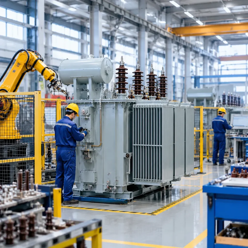
Our production facility utilizes modern machinery to ensure tight tolerances and structural longevity across every unit:
Automated Core Assembly: CNC slitting and automated step-lap stacking minimize core vibration and drastically reduce no-load excitation losses.
Precision Coil Winding: Automated horizontal and vertical winding machines handle oxygen-free electrolytic copper conductors with uniform mechanical tension.
Vacuum Drying Chambers: Deep-vacuum moisture extraction processes guarantee optimal insulation dry-out, extending dielectric life and asset durability.
Tailored Solutions Across Grid & Industrial Sectors
We eliminate the constraints of standard catalog units by building custom kVA and MVA ratings for challenging operating environments:
Harsh Environments: Specialized thermal dissipation designs for extreme desert heat, high-altitude installations, and corrosive coastal areas.
Seismic and Heavy Industrial Applications: Reinforced mechanical bracing capable of withstanding heavy vibration, dynamic load fluctuations, and high-seismic requirements, including rugged power transformer solutions for the mining industry.
Flexible Footprints: Customized physical dimensions and bushing layouts engineered for seamless drop-in substation retrofits.
End-to-End Quality Verification
Every transformer undergoes strict quality control before it leaves our manufacturing floor:
Comprehensive Testing: 100% factory routine and dielectric testing under international standards (IEC, IEEE, ANSI).
Grid-Ready Deployment: Complete factory pre-commissioning checks ensure fast site installation and immediate, trouble-free grid synchronization.
Step-by-Step Request for Quotation (RFQ) Specification Guide
Submitting a clear, comprehensive data sheet directly to our engineering team accelerates technical evaluation, prevents scope mismatch, and ensures you receive an accurate commercial proposal without delay. As a dedicated manufacturer of power transformer units, we build to exact site requirements, balancing performance, reliability, and lifecycle costs.
Core Technical Parameters
To initiate electromagnetic modeling for your electrical substation transformer or distribution unit, our design team requires the fundamental electrical ratings:
-
- Rated Capacity (kVA / MVA): Base rating and maximum stage capacity under forced cooling.
- Voltage Ratio & Frequency: Primary (HV) and secondary (LV) nominal voltages, operating at 50 Hz or 60 Hz.
- Vector Group Connection: Standard configurations such as Dyn11, YNd11, or custom phase-displacement requirements.
- Tapping Configuration: Off-Circuit Tap Changer (OCTC) or On-Load Tap Changer (OLTC), including tap steps (e.g., ±2 × 2.5%).
Operational & Loss Parameters
Defining boundary conditions upfront enables our engineers to calculate core-and-winding profiles, short-circuit withstand capabilities, and overall efficiency:
| RFQ Parameter | Standard Specification / Options | Engineering Purpose |
|---|---|---|
| Cooling Method | ONAN, ONAF, OFAF, or KNAN (Ester) | Determines radiator sizing and thermal dissipation margins |
| Short-Circuit Impedance (%Z) | Typically 4.0% to 12.5% (per standard/rating) | Controls fault current levels and voltage regulation |
| Guaranteed Losses | Maximum No-Load (Core) & Load Losses (kW) | Establishes total cost of ownership and energy efficiency |
| Ambient & Environmental Limits | Temperature extremes, altitude (>1000m), seismic zones | Dictates insulation levels, bushing creepage, and tank design |
| Standards Compliance | IEC 60076, IEEE C57, or regional grid codes | Aligns testing and manufacturing tolerances with local regulations |
Direct Engineering Consultation
Skip the communication lag of third-party middlemen. When you send your project data sheet to our factory, our senior electrical and mechanical engineers review the specifications directly. We clarify installation envelopes, terminal arrangements, and protection accessories right away. For complex regional projects, you can review our power transformer procurement guide to align your site data before submitting an RFQ for custom power transformer fabrication.
Frequently Asked Questions About Choosing a Manufacturer of Power Transformer
What is the typical lead time for a custom high-voltage power transformer?
Lead times depend on raw material availability and design complexity. As a direct manufacturer of power transformer units, we typically work within these timelines:
| Transformer Type | Standard Capacity / Class | Typical Production Lead Time |
|---|---|---|
| Standard Distribution Units | Medium voltage (up to 35 kV) | 6 to 10 weeks |
| Cast Resin Dry-Type Units | Commercial / indoor industrial | 8 to 12 weeks |
| High Voltage Power Transformers | Transmission / Substation (69 kV – 230 kV+) | 16 to 24+ weeks |
Engineering approvals, specialized tap-changers, and third-party witness testing can adjust these schedules. Direct communication with our factory engineering team helps lock in production slots early to avoid site delays.
How do factory loss evaluations impact overall project lifecycle costs?
Upfront purchase price (CAPEX) accounts for only a fraction of total lifetime expenditure. The remaining cost comes from operational losses over decades of service:
-
- No-Load Losses (Core Losses): Constant power consumed by core magnetization 24/7, regardless of load. Optimized using high-grade CRGO steel.
- Load Losses (Winding Losses): Variable energy dissipated as heat when current flows through conductors. Minimized using high-purity electrolytic copper windings.
Specifying capitalized loss evaluation formulas ($/kW for no-load and load losses) during RFQ allows us to engineer the exact balance between initial build cost and long-term operating efficiency.
What documents should be included in the Factory Acceptance Test (FAT) dossier?
Before any transformer leaves our floor, we provide a complete, verified quality package containing:
Routine Test Reports: Voltage ratio, vector group verification, winding resistance, insulation resistance, no-load loss, and load loss measurements.
Dielectric Test Data: Separate-source AC withstand and induced overvoltage test logs.
Material Test Reports (MTR): Mill test certificates for core steel, conductor copper, and insulating fluids.
Type & Special Test Records: Temperature rise data, lightning impulse reports, and sound level measurements where contracted.
Calibration Records: Current calibration certificates for all testing station instrumentation.
How do I determine whether to choose oil-immersed or dry-type transformers for my facility?
The choice between fluid-filled and dry units depends on the installation environment, safety regulations, and footprint limits:
-
- Choose Dry-Type Transformers: Best for indoor commercial facilities, hospitals, high-rise buildings, underground substations, and environments where oil containment or fire hazard is a concern. Our SCB-11 dry-type power transformer series provides high flame retardancy and minimal maintenance for clean indoor layouts.
- Choose Oil-Immersed Transformers: Preferred for outdoor substations, heavy industrial facilities, utility distribution, and large utility-scale renewable step-up applications where higher MVA ratings and maximum cooling efficiency are essential.
Related Sources
- https://e-cigre.org/publication/530-guide-for-conducting-factory-acceptance-tests-for-power-transformers
- https://www.se.com/ww/en/download/document/998-2095-10-14-15AR0_EN/
- https://www.copper.org/environment/sustainable-energy/transformers/education/losses.html
- https://www.hitachienergy.com/products-and-solutions/transformers/power-transformers