
Core Configurations: Oil-Immersed vs. Dry-Type 1000 kVA Transformers
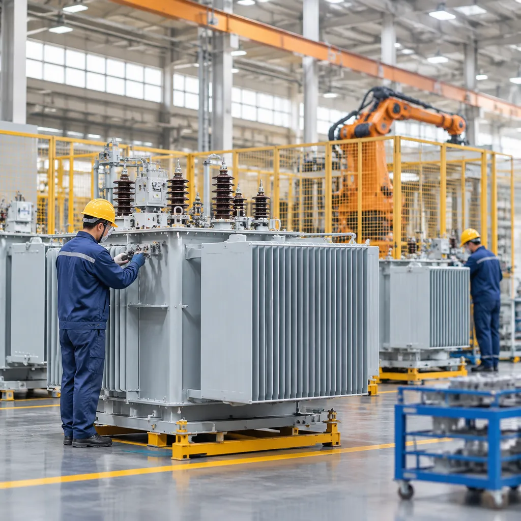
Procuring a 1000 kVA unit starts with one fundamental decision: liquid-filled or cast resin. As a dedicated transformer 1000 kva manufacturer, we build both configurations in-house to match precise environmental demands, site constraints, and total cost targets.
1000 kVA Oil-Immersed Transformer: Built for Endurance
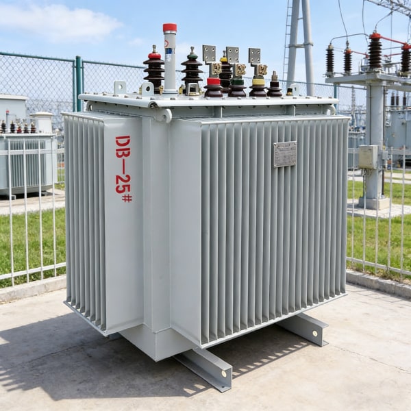
Our 1000 kVA oil immersed transformer units are engineered for robust power distribution in utility grids and heavy industrial installations.
- Core Construction: Built with high-permeability, low-loss CRGO silicon steel cores to minimize excitation currents and lower no-load losses.
- Cooling Systems: Standard ONAN (Oil Natural Air Natural) for self-cooling, with optional ONAF (Oil Natural Air Forced) fan packages for handling continuous peak loads.
- Sealed Integrity: Fully sealed corrugated tanks or conservator designs that protect the dielectric insulating oil from ambient moisture and oxidation.
- Lifecycle Value: Exceptional thermal dissipation that extends operational life even under harsh, continuous-duty outdoor conditions.
Cast Resin Dry-Type 1000 kVA Transformer: Zero-Fire Hazard
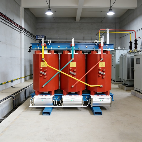
For installations where fire safety and environmental restrictions eliminate liquid dielectrics, our 1000 kVA dry type transformer delivers dependable performance without containment vaults.
- Insulation Safety: High-grade Class F (155°C) or Class H (180°C) insulation systems utilizing vacuum cast resin encapsulation.
- Fire Retardant: Self-extinguishing materials that generate low smoke and no toxic gas emissions during thermal distress.
- Maintenance Free: Moisture-resistant and dust-resistant windings require virtually zero scheduled maintenance beyond basic thermal scanning.
- Zero Leakage Risk: Eliminates ground-spill risks, making it ideal for environmentally sensitive locations.
Configuration Comparison
| Feature | 1000 kVA Oil-Immersed | 1000 kVA Cast Resin Dry-Type |
|---|---|---|
| Cooling Medium | Mineral oil / Synthetic fluid (ONAN/ONAF) | Ambient air (AN/AF) |
| Insulation Class | Class A (105°C) | Class F (155°C) / Class H (180°C) |
| Core Material | High-grade CRGO silicon steel | High-grade CRGO silicon steel |
| Fire Safety Requirement | Oil containment pit & blast walls | No special fire-containment measures |
| Installation Footprint | Larger clearance required | Compact, modular integration |
| Maintenance Level | Oil sampling & seal checks | Visual inspection & dusting |
Application Match: Outdoor Substations vs. Indoor Facilities
Selecting between these two builds depends on your deployment environment and local safety codes:
- Outdoor Substations & Heavy Industry: Oil-filled units are the standard for outdoor utility pads, processing plants, mining, and open switchyards where thermal resilience and weather resistance are paramount.
- Commercial & Indoor Facilities: Dry-type cast resin units are the mandatory choice for hospitals, high-rise buildings, underground vaults, data centers, and commercial hubs where non-flammable operation directly protects human life and property.
Critical Technical Specifications to Review with Your 1000 kVA Transformer Manufacturer
When you sit down with a transformer 1000 kva manufacturer, vague requirements lead to unexpected losses, delayed factory sign-offs, and switchgear mismatches. We work through these core electrical parameters upfront to ensure your equipment fits the exact operational and financial goals of your site.
Copper vs. Aluminum Windings: Performance and Cost
Choosing conductor material directly dictates thermal endurance, footprint, and total capital expenditure:
| Parameter | High-Conductivity Copper Winding | Electrical-Grade Aluminum Winding |
|---|---|---|
| Footprint & Weight | Compact enclosure, higher mass density | 20–30% larger enclosure required |
| Short-Circuit Withstand | Excellent mechanical rigidity against mechanical stress | Moderate; requires beefier structural bracing |
| Thermal Expansion | Lower expansion rate; tight joint integrity | Higher thermal expansion; requires specialized lugs |
| Initial Cost | Higher initial purchase price | 15–25% lower upfront material cost |
For industrial setups with heavy cyclic loads or space-constrained substations, a copper winding transformer provides maximum resilience and smaller physical dimensions. Aluminum is a solid, budget-conscious alternative if substation footprint is not a limiting factor.
Selecting the Right Percentage Impedance (%Z)
A unit’s transformer impedance voltage determines both the fault current level delivered to downstream switchgear and the voltage drop under load:
- Standard Rating: For a 1000 kVA rating, standard impedance generally sits between 5.0% and 5.75% (per IEC and ANSI benchmarks).
- Lower %Z (< 5.0%): Delivers tighter voltage regulation during motor starting, but dramatically increases prospective fault currents, forcing you to purchase costlier high-AIC downstream breakers.
- Higher %Z (> 6.0%): Limits fault currents to protect existing switchgear, but introduces noticeable voltage sag during peak transient draws.
Evaluating No-Load and Load Losses
Purchase price represents only a fraction of the total cost of ownership transformer calculation over a 25-year lifespan. We separate losses into two distinct categories:
- Transformer No-Load Losses (Core Losses): Present 24/7 regardless of load. We use premium, cold-rolled grain-oriented (CRGO) silicon steel cores to keep continuous magnetic hysteresis and eddy currents at absolute minimums.
- Load Losses (Winding Losses): Scale with the square of the current ($I^2R$). Matching these losses to your actual operating profile prevents wasted utility dollars.
Evaluating these figures alongside our guide on understanding power transformers and distribution transformers ensures your operational duty cycle matches your loss capitalization formula.
Vector Groups and Tap Changer Selection
- Vector Configuration: For 1000 kVA commercial and industrial installations, Dyn11 is our primary configuration. The delta primary isolates third-harmonic zero-sequence currents, while the star secondary with a neutral point readily accommodates unbalanced single-phase lighting and three-phase motor circuits.
- Off-Circuit Tap Changers (OCTC): Standard units feature a manual 5-position switch (± 2 × 2.5%) adjusted only when the unit is de-energized.
- On-Load Tap Changers (OLTC): Necessary when the incoming medium-voltage grid experiences constant fluctuations and sensitive production equipment cannot tolerate voltage swings.
Manufacturing Standards and Regulatory Compliance Benchmarks
When sourcing heavy electrical equipment, compliance cannot be an afterthought. As a dedicated transformer 1000 kva manufacturer, we engineer every unit around strict international benchmarks to ensure seamless utility interconnection, worker safety, and predictable long-term operating costs.
Global Utility and Safety: IEC 60076 vs. IEEE C57
Different regions demand different engineering rules. We tailor our core-and-coil designs to match your regional grid codes:
- IEC 60076 Standards: Standard practice across Europe, Asia, and the Middle East. Focuses on temperature rise limits (typically 60/65K for oil, Class F/H for dry-type), standardized insulation levels, and specific short-circuit withstand tolerances.
- IEEE C57 / ANSI Standards: Common across North America and select Latin American markets. Specifies rigorous insulation power factor metrics, seismic withstand capability, and standard BIL (Basic Impulse Insulation Level) ratings.
Whether you need specialized municipal grid compliance or factory-direct power transformer solutions for Poland distributors and contractors, our production line conforms strictly to ISO 9001:2015 quality controls.
Efficiency Mandates: Meeting DOE and Ecodesign Targets
Local energy regulations directly govern allowed transformer losses. Installing non-compliant equipment can lead to failed utility sign-offs and heavy operational fines.
| Regulation / Standard | Target Region | Core Design Strategy | Primary Benefit |
|---|---|---|---|
| DOE 10 CFR Part 431 | North America | High-grade CRGO silicon steel, optimized magnetic flux density | Drastically lowers no-load idle losses |
| EU Ecodesign (Tier 2) | European Union | Step-lap mitered core joints and high-conductivity copper windings | Cuts peak load losses and carbon footprint |
| Standard Baseline | Developing Markets | Balanced copper/aluminum options matching regional utility tiers | Lowers initial capital cost while remaining reliable |
Enclosure Ratings: IP00 Open Frames to NEMA 3R and IP54
Environmental conditions dictate the mechanical envelope of your transformer. We build custom-rated housings to protect active components against dust, moisture, and chemical exposure:
- IP00 / Open Frame: Built without an external housing. Ideal for clean, climate-controlled indoor electrical vaults or direct integration inside third-party switchgear panels.
- IP21 / IP23 / NEMA 1 (Indoor Ventilated): Provides basic drip-proof and foreign-object protection for commercial basements, mechanical rooms, and industrial plants.
- IP54 / NEMA 3R (Outdoor Weatherproof): Standard protection level for outdoor installations. Keeps out windblown rain, sleet, snow, and dust while maintaining adequate passive airflow or radiator cooling.
- NEMA 4X / Heavy-Duty Stainless Enclosures: Designed for corrosive coastal settings, chemical processing sites, and washdown zones where standard powder-coated steel degrades rapidly.
Factory Acceptance Testing (FAT) and Quality Verification Steps
When you source equipment directly from a transformer 1000 kva manufacturer, thorough factory testing is your best insurance policy against premature field failure, improper tap voltage ratios, and efficiency penalties. We perform strict quality verification on every unit—whether it is an oil-filled substation unit or a cast resin dry-type model—to verify that calculated design figures match physical operational benchmarks.
Essential Routine Tests: Winding Resistance, Turns Ratio, and Dielectric Withstand
Routine testing occurs on 100% of our production run before equipment is cleared for crating. These non-destructive evaluations confirm baseline electrical integrity:
- Winding Resistance Measurement: Verified across all phases and tap positions using high-precision digital micro-ohmmeters. This confirms balanced conductor paths, tight crimps, and correct coil terminations.
- Voltage Ratio and Vector Group Verification: Confirms that the turns ratio matches your specified primary and secondary voltage steps exactly, verifying angular phase displacement (such as Dyn11) to prevent phase-angle mismatches during parallel operation.
- Insulation Resistance & Dielectric Withstand: Applied voltage and separate-source AC withstand tests, alongside induced overvoltage testing at elevated frequencies, stress the primary insulation barriers to confirm there are no dielectric breakdowns or partial discharge issues.
- Loss and Impedance Measurements: Accurate no-load loss (core loss) and load loss (copper loss) measurements at rated current verify that our high-grade CRGO cores and winding geometries meet contracted efficiency levels.
| Routine Test Stage | Parameter Verified | Standard Acceptance Criteria |
|---|---|---|
| Turns Ratio & Phase Displacement | Voltage transformation ratio | Within ±0.5% of design values |
| Winding Resistance | DC conductor continuity | Phase balance within strict IEC/IEEE tolerances |
| Dielectric Power Frequency | Major insulation barrier strength | Withstand test voltage for 60 seconds without breakdown |
| No-Load Loss & Current | Magnetizing performance of core | Strictly within guaranteed contract wattage |
Type and Special Testing: Lightning Impulse, Temperature Rise, and Acoustic Checks
Beyond basic routine checks, critical industrial and utility installations require design validation under harsh mechanical and thermal stresses. As an experienced manufacturer of power transformer for reliable energy, our facility supports comprehensive type and special testing protocols:
- Full-Wave Lightning Impulse Withstand: We simulate transient atmospheric surges and switching overvoltages using high-voltage impulse generators, ensuring the insulation system safely handles grid disturbances without internal tracking.
- Temperature Rise Run: Continuous full-load heat runs verify that winding hot spots and top-oil temperatures stay well within design insulation classes (such as Class F/H for dry units or standard 65°C rise limits for oil-immersed models).
- Acoustic Sound Level (dB) Testing: Calibrated decibel measurements taken in low-ambient sound chambers confirm compliance with NEMA and IEC standards, ensuring quiet operation for commercial buildings, hospitals, and dense urban substations.
Evaluating Manufacturer Test Reports and Quality Audits
Every completed 1000 kVA transformer ships with a certified, traceable Factory Acceptance Testing (FAT) data book. We invite clients and third-party inspectors to witness physical FAT runs or review live digital test feeds.
Our operations adhere to ISO 9001:2015 quality management procedures, covering raw material verification—such as core loss grading on imported silicon steel and purity verification on electrolytic copper—through to final paint thickness checks and tank leak testing under positive pressure. Reviewing these verified factory test values against your purchase specifications ensures total compliance before the hardware ever hits your site.
Custom Engineering Options for 1000 kVA Substation Integration
Off-the-shelf units rarely drop into existing facilities without friction. As an experienced transformer 1000 kva manufacturer, we build custom electrical configurations tailored directly to site layouts, primary grid feeds, and operational monitoring needs.
Tailored Primary Voltage Steps
Grid connections vary widely across regional utility networks and private industrial plants. We configure our step-down transformer 1000 kVA designs to match your precise incoming medium-voltage levels:
- Primary Voltages: 11 kV, 13.8 kV, 22 kV, and 33 kV setups.
- Secondary Outputs: Standard 400V, 415V, or 480V low-voltage supplies, with dual-voltage output options available.
- Tappings: Off-circuit tap changers (OCTC) with ±2×2.5% settings, or on-load tap changers (OLTC) for networks prone to voltage swings.
| Parameter | Standard Configuration | Custom Option |
|---|---|---|
| Primary Voltage | 11 kV or 13.8 kV | 22 kV, 33 kV, or dual-input |
| Secondary Voltage | 400V / 415V / 480V | Multi-tap custom LV distribution |
| Connection Scheme | Dyn11 standard delta-wye | YNd11, Dyn5, or custom phase shifts |
| Bushing Types | Standard porcelain bushings | Plug-in separable connectors / elbow bushings |
Footprint Optimization for Compact Substations and Retrofits
Replacing an aging unit or slotting equipment into tight switchgear rooms demands exact mechanical dimensions. We engineer custom base channels, bus duct throat connections, and cable box orientations to match your existing footprint without field rework.
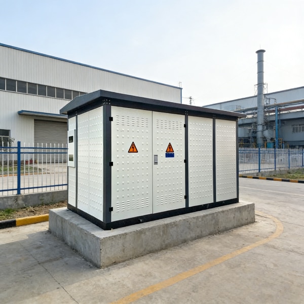
For turnkey exterior projects, our engineering team integrates these units into a pre-engineered box-type transformer substation, ensuring the high-voltage gear, 1000 kVA transformer, and low-voltage panels share a compact, weatherproof enclosure.
Condition Monitoring Add-Ons
Preventing unplanned downtime requires real-time insight into thermal and mechanical stresses. We equip our 1000 kVA units with targeted instrumentation packages:
- Oil-Immersed Protection: Multi-stage Buchholz relays for gas collection and surge tripping, oil level gauges with low-level contacts, and pressure relief devices (PRD) with direct alarm outputs.
- Dry-Type Thermal Monitoring: Embedded PT100 resistance temperature detectors in each phase winding paired with multi-channel digital controllers for automated fan cooling and trip sequencing.
- Smart Integration: RS-485 Modbus communication interfaces on all gauges to send live thermal and pressure data straight to your facility SCADA or PLC network.
Commercial Sourcing: Managing Lead Times, Freight, and RFQs
Sourcing directly from a transformer 1000 kva manufacturer cuts procurement markups, but managing project schedules requires visibility into factory queues, raw material flows, and international logistics. As an engineering-driven production team, we help buyers avoid common bottlenecks by outlining exact manufacturing stages and shipping safeguards upfront.
Key Production Timeline Drivers
A standard build schedule for a 1000 kVA unit ranges from 6 to 12 weeks, dictated by three main bottlenecks:
- Core Steel Sourcing: High-grade CRGO (Cold Rolled Grain Oriented) silicon steel must be laser-cut, slit, and step-lap stacked. Supply chain tight spots in electrical steel can impact early milestones.
- Winding & Curing: Precision copper or aluminum winding requires dedicated winding machine slots. Dry-type cast resin coils demand precise vacuum casting and mold curing cycles, while oil units require extensive vacuum drying of the active part before tanking.
- Factory Test Queue: Routine dielectric and ratio testing, followed by witnessed Factory Acceptance Testing (FAT), requires allocated test bay time before packing.
| Production Phase | Typical Duration | Critical Engineering Gate |
|---|---|---|
| Design & Engineering Review | 1–2 Weeks | Approval of technical data sheets & outline drawings |
| Core Slitting & Coil Winding | 3–5 Weeks | Material quality verification (CRGO & conductor purity) |
| Assembly, Drying & Tanking | 2–3 Weeks | Vacuum moisture extraction & core-coil clamping |
| FAT & Final Coating | 1–2 Weeks | Dielectric, loss tests & multi-layer surface treatment |
Seaworthy Export Packaging and Logistics
A 1000 kVA unit weighs between 3,000 kg and 4,500 kg depending on whether it is an oil-immersed or cast resin build. Protecting that mass during ocean or road transit requires robust packing standards:
- Reinforced Skid Mounts: Heavy-duty wooden skids built for forklift handling, container lashing, or flat-rack securing.
- Corrosion Barriers: Vapor-corrosion inhibitor (VCI) shrink wrap and industrial desiccant bags prevent moisture ingress inside marine containers.
- Transit Shock Monitoring: Single-use impact indicators (ShockWatch) and tilt sensors are fitted to the tank or enclosure to monitor mechanical stress during port crane transfers.
- Fluid Management for Liquid Units: Nitrogen-blanketed shipments or hermetically sealed, factory-filled oil configurations are arranged based on project site handling rules. For deep dives into international logistics and customs handling, review our oil-immersed transformer import guide to keep port clearances seamless.
RFQ Checklist: What to Submit for a Firm Quote
To avoid multiple revisions and get an accurate bid on your first inquiry, provide these baseline parameters:
- Core Ratings: 1000 kVA nominal rating, primary voltage (e.g., 11 kV, 13.8 kV, 33 kV), and secondary output (e.g., 400 V, 480 V).
- Transformer Type: Liquid-filled (mineral oil or ester fluid) or cast resin dry-type.
- Target Losses & Impedance: Guaranteed maximum no-load (core) losses, load (copper) losses, and required impedance (%Z).
- Vector Group & Taps: Vector configuration (standard Dyn11) along with off-circuit tap changer (OCTC) range (e.g., ±2×2.5%) or on-load tap changer (OLTC).
- Environmental Context: Ambient temperature limits, installation altitude (if above 1,000 m), and outdoor enclosure ratings (NEMA 3R, IP54).
- Documentation: Single-Line Diagrams (SLD) and connection terminal constraints (cable boxes vs. open bushings) to verify physical clearances.
Frequently Asked Questions on Sourcing a 1000 kVA Transformer
How do I choose between an oil-immersed and a dry-type 1000 kVA unit?
The choice comes down to installation location, local fire codes, and maintenance requirements. As an experienced transformer 1000 kva manufacturer, we guide buyers through the primary physical differences:
| Feature | 1000 kVA Oil-Immersed Transformer | 1000 kVA Dry-Type Transformer |
|---|---|---|
| Best Placement | Outdoor substations, industrial yards | Indoor electrical rooms, high-rise buildings |
| Cooling Method | Mineral oil (ONAN / ONAF) | Natural/forced air circulation (AN / AF) |
| Fire Safety | Requires oil containment pits & clear spacing | Self-extinguishing cast resin, zero fluid risk |
| Footprint & Weight | Heavier, compact core profile | Lighter overall, larger enclosure volume |
| Upfront Cost | Lower initial capital expenditure | 15% to 30% higher capital investment |
For outdoor commercial substations with sufficient perimeter clearance, a factory-direct oil-immersed transformer provides the highest thermal efficiency. For hospitals, commercial towers, and mines where fire codes prohibit combustible fluids, our cast resin dry-type transformer solutions provide safe, maintenance-free operation.
What is the typical production lead time from a direct transformer manufacturer?
Factory lead times for a 1000 kVA unit depend on component availability and customization level:
- Standard builds (IEC / IEEE baseline): 6 to 8 weeks from approved approval drawings.
- Custom-engineered units: 8 to 12 weeks for non-standard primary voltages, special impedance ratings, or harsh-environment NEMA 4X / IP54 enclosures.
- Production bottlenecks: The main drivers are procurement schedules for high-grade CRGO silicon steel, custom copper conductor sizing, and high-voltage factory acceptance testing (FAT) slots.
What data do I need to prepare before requesting a 1000 kVA quote?
To give you an accurate, binding proposal without back-and-forth delays, our engineering team requires these key specifications:
- Primary and Secondary Voltages: e.g., 11 kV, 13.8 kV, or 33 kV stepped down to 400 V, 480 V, or 208 V.
- Winding Material: Copper (highest thermal endurance) or Aluminum (budget-optimized).
- Impedance Voltage (%Z): Standard 4.5% to 6% depending on your downstream fault-level limits.
- Vector Group: Standard Dyn11 or special utility winding configurations.
- Environmental Profiles: Maximum ambient operating temperature, altitude (if exceeding 1,000 meters), and indoor vs. outdoor setup.
- Loss Guarantees: Efficiency benchmarks matching IEC 60076, North American DOE 2016, or EU Ecodesign Tier 2 standards.
Can a 1000 kVA transformer handle dual-voltage inputs or custom tap ranges?
Yes. We regularly build custom dual-voltage primary windings (such as switchable 11 kV / 22 kV or 13.8 kV / 4.16 kV systems) for facilities expecting grid reconfigurations or operations across multiple deployment zones.
Standard units come equipped with a 5-position off-circuit tap changer (OCTC) configured for ±2×2.5% regulation. When site conditions face unstable primary grid supply, we engineer customized tap ranges (such as ±5% or 7-position switches) or integrate on-load tap changers (OLTC) for real-time voltage adjustment under continuous load.